
Manual

Integrating Axes
Chapter 9
99
4. Jog the axis in either direction at maximum speed (rapid traverse rate
with 127% feedrate override). If you don’t have enough axis travel
in which to adjust the potentiometer, disconnect the servo motor
from the leadscrew as in the open-loop procedure (see section titled
“Open-loop Procedure,” in this chapter). Set the potentiometer (see
section titled “Connecting the Tachometer,” in chapter 6) for a 50V
maximum tachometer signal at the 1771-ES expander.
5. If the tachometer voltage is less than 10V, enter a conversion factor
in the last word of the parameter block. The conversion factor
multiplied by the full scale velocity command voltage must be a
value less than the tachometer voltage.
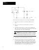
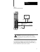
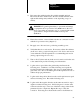
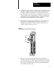
Figure 9.3
1771ES
Expander T
est Points and Potentiometers
11066
White
Tach
Coarse
Tach
Fine
Yellow
6. With power off, remove the potentiometer from between the
tachometer signal and the 1771-ES expander. Measure the resistance
the potentiometer was providing. Replace the potentiometer with a
fixed resistor of equivalent value to limit the tachometer signal into
the 1771-ES expander to 50V.