
Manual

Chapter 8
816
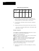
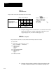
Nominal Time (ms) per Block Transfer
Channels
with
BlockTransfer
Modules
1 Active
Channel
2 Active
Channels
3 Active
Channels
4 Active
Channels
1 40 52 54 58
2 67 68 76
3 98 99
4 123
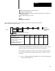
4. Count the number of block-transfer modules on the channel. If a
chassis containing block-transfer modules is repeated in the chassis
scanning sequence list, count the modules as often as listed.
5. Count the number of I/O chassis entries in the chassis scanning list
for the channel.
6. Calculate the time between block transfers for the scanner as follows:
scanner time = [nominal time x BT modules on the channel] + [I/O
chassis in list -1) x 9ms
Example Computation
As an example, we compute the read/write block transfer time for each of
two 1771-M3 controllers in the following system:
User program contains 20K words.
Channel 1 contains five I/O chassis, with a total of seven block-transfer
modules including one 1771-M3 controller.
Channel 2 contains two I/O chassis with no block-transfer modules.
Channel 3 contains two I/O chassis with one 1771-M3 controller.
Channel 4 is made inactive thru LIST.
You can compute the read/write block transfer times for the 1771-M3
controllers in this example in four steps. An accompanying figure
explains each of the following four steps.
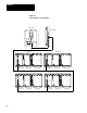
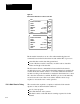
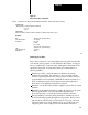
1. Diagram the I/O channels of your PC system (Figure 8.6), showing
the number of: