
Manual

Chapter 8
85
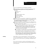
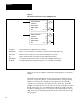
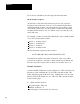
Figure 8.3
Blocktransferreadinstruction
Example (PLC2/30 or MiniPLC2/15)
1
R
Block length code
Data Table
121
1
R
060
010
012
017
027
030
110
112
117
130
Output Image Table
Byte contains Read
Enable Bit and Block
Length in binary code.
Data Address contains
Module Address in BCD
Input Image Table Byte
contains Done Bit
Storage location of file
address in BCD
First file word
Last file word
EN
BLOCK XFER READ
DATA ADDR:
MODULE ADDR:
BLOCK LENGTH:
FILE:
030
121
00
060- 067
DN
012
17
112
17
Output
Image
Table
Timer/
Counter
Accumulated
Area
Input
Image
Table
Timer/
Counter
Preset
Area
11057
Block Transfer Data
060
067
R = Bit 17 = READ
113
02