
Manual

Formatting and Interpreting Data Blocks
Chapter 7
731
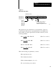
% Excess Following Error
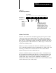
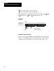
The % excess following error parameter is a 2-digit BCD number that the
1771-ES expander interprets as a percentage above the following error
allowed at the rapid traverse rate. Programmable excess following error
values can thus range from 0 through 99. Program the most significant
digit in bits 14 through 17 of the first word, and the least significant digits
in bits 14 through 17 of the second word (Figure 7.21).
This parameter specifies maximum allowable axis following error. When
the following error reaches the maximum value permitted as specified by
the % excess following error parameter, the servo positioning assembly
stops axis motion by commanding immediate stop (Figure 7.16).
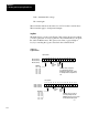
Figure 7.21
Excess Following Error
, D/A V
oltage W
ords
17161514131211100706050403020100
% Excess Following Error (MSD), +D/A Voltage
Word 15 (Axis 1)
Word 34 (Axis 2)
Word 53 (Axis 3)
Most significant
digit of excess
following error
percentage, BCD
format.
Maximum + D/A voltage
(analog output voltage),
BCD format. For +10.0V,
program 000.
17161514131211100706050403020100
% Excess Following Error (LSD), -D/A Voltage
Word 16 (Axis 1)
Word 35 (Axis 2)
Word 54 (Axis 3)
11043
Least significant
digit of excess
following error
percentage, BCD
format.
Maximum D/A voltage
(analog output voltage),
BCD format. For 10.0V,
program 000.
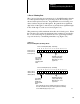
Excess following error percent should be greater than or equal to 6%.
The value entered here is the percent above rapid traverse following
error at which Emergency Stop is to occur.