Allen Bradley Servo Positioning Assembly (Cat. No.
Table of Contents Using This Manual . . . . . . . . . . . . . . . . . . . . . . . . . . . . . . . 1 1 Manual's Purpose . . . . . . . . . . . . . . . . . . . . . . . . . . . . . . . . . . . Audience . . . . . . . . . . . . . . . . . . . . . . . . . . . . . . . . . . . . . . . . . . Vocabulary . . . . . . . . . . . . . . . . . . . . . . . . . . . . . . . . . . . . . . . . Manual Organization . . . . . . . . . . . . . . . . . . . . . . . . . . . . . . . . .
ii Table of Contents Installing the Assembly . . . . . . . . . . . . . . . . . . . . . . . . . . . 6 1 Chapter Objectives . . . . . . . . . . . . . . . . . . . . . . . . . . . . . . . . . . . Configuring the Modules . . . . . . . . . . . . . . . . . . . . . . . . . . . . . . . Setting Switches and Jumpers . . . . . . . . . . . . . . . . . . . . . . . . . . Keying . . . . . . . . . . . . . . . . . . . . . . . . . . . . . . . . . . . . . . . . . . . Inserting the Module . . . . . . . . . . . . . . . . . .
Table of Contents iii Glossary . . . . . . . . . . . . . . . . . . . . . . . . . . . . . . . . . . . . . . A 1 Status Block . . . . . . . . . . . . . . . . . . . . . . . . . . . . . . . . . . . B 1 Parameter Block . . . . . . . . . . . . . . . . . . . . . . . . . . . . . . . . C 1 Moveset Block . . . . . . . . . . . . . . . . . . . . . . . . . . . . . . . . . . 6 1 Command Block . . . . . . . . . . . . . . . . . . . . . . . . . . . . . . . .
Chapter 1 Using This Manual Manual's Purpose This manual shows you how to use the series B Servo Positioning Assembly (cat. no. 1771-QC). If you have a series A Servo Positioning Assembly, refer to publication 1771-817. Audience To use the servo positioning assembly, you must be able to program and operate an Allen-Bradley PC processor. In particular, you must be able to program block transfer instructions. In this manual, we assume that you know how to do this.
Chapter 1 Troubleshooting Manual Organization This manual is organized into the following chapters: Chapter 1 2 Title What's Covered 2 Introducing the Servo Positioning Assembly an overview of the servo positioning assembly, its applications, functions, and features 3 Positioning Concepts concepts of closed loop positioning, including velocity loop, positioning loop, and feed forward 4 Positioning with Allen Bradley PC's the servo positioning assembly's position in a servo system, and the serv
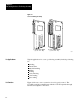
Chapter 2 Introducing the Servo Positioning Assembly Chapter Objectives This chapter gives you an overview of the servo positioning assembly, its applications, functions and features. What is the Servo Positioning Assembly? A servo positioning assembly controls the motion of one of your axes. It consists of: one Servo Controller Module (cat. no.1771-M3) one Servo Expander Module (cat. no. 1771-ES) that includes two Field Wiring Arms (cat. no.
Chapter 2 Introducing the Servo Positioning Assembly Figure 2.1 Servo Positioning Assembly (a) Servo Controller Module (cat. no. 1771 - M3) Its Applications (b) Servo expander Module (cat. no. 1771 - ES) 17954 Typical applications for a servo positioning assembly include positioning for: grinding transfer lines material handling drilling riveting rotary indexing v-belt cutting glass cutting Its Function 2 2 Figure 2.2 shows a servo system for closed-loop axis control.
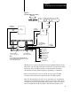
Chapter 2 Introducing the Servo Positioning Assembly Figure 2.2 Closed loop Axis Servo System Axis Motion Motor Tach Velocity Feedback Command Position Data Status Block Encoder Velocity Command PC Processor Servo Drive Drive Disable Tach Input for Loss-of-Feedback Detection Position Feedback Discrete Inputs: Jog Forward Jog Reverse Servo Controller (cat. no. 1771 -M3) Servo Expander (cat. no.
Chapter 2 Introducing the Servo Positioning Assembly feedback from your encoder. The 1771-ES expander is able to provide this fast servo sample rate because the update is independent of the I/O scan. A drive-disable output provides a signal to disable the servo drive in conditions such as loss-of-feedback or a hardware-stop signal. A hardware-done output signals the completion of each single-step move.
Chapter 2 Introducing the Servo Positioning Assembly Feature Benefit incremental digital encoder feedback precise closed loop positioning absolute or incremental positioning commands programming flexibility programmable gain break precise positioning at low speed with stability at high speed programmable acceleration/deceleration optimize the machine cycle time over varying loads programmable in position band flexible positioning accuracy programmable jog rates flexible manual positioning pro
Chapter 2 Introducing the Servo Positioning Assembly Feature Benefit optically isolated analog output[1] guards against noise entering the backplane circuits and limits the potential for damage due to improper connection external hardware start[1] synchronizes moves with other axes encoder input selectable for high true or low true[1] synchronized start of feedrate override[1] sensing of customer power supply loss[1] feed forwarding[1] constant velocity command[1] moveset override[1] diagnostic
Chapter 2 Introducing the Servo Positioning Assembly [1]These features are only available on the series B servo positioning assembly. Summary This chapter was intended to be very general. Upcoming chapters cover these topics in greater detail. To prepare for those details, read about positioning concepts in chapter 3.
Chapter 3 Positioning Concepts Chapter Objectives This chapter presents positioning concepts and terminology. If you are thoroughly familiar with the concepts of closed-loop servo positioning, you can skip ahead to chapter 4. Closed Loop Positioning Closed-loop positioning is a precise means of moving an object from one position to another. Typically, an electric motor supplies the mechanical power, and the needed motion is linear.
Chapter 3 Positioning Concepts Velocity Loop Most closed-loop servo positioning installations use a dc motor to power the leadscrew. To accurately control the velocity of the dc motor, we need a velocity loop (Figure 3.2). The velocity loop contains a summing point, an amplifier, and a tachometer. A tachometer is a precision generator that produces a voltage signal directly proportional to the angular velocity of the motor shaft.
Chapter 3 Positioning Concepts Positioning Loop When we want to move the slide a specific distance, we can turn the motor on at a specific velocity for a specific length of time. However, this could produce imprecise positioning. To accurately control the position of the slide, we need a positioning loop (Figure 3.3). Figure 3.
Chapter 3 Positioning Concepts to generate the velocity command. Gain is expressed in ipm/mil (where 1 mil - 0.001 in) or mmpm/mil (where 1 mil = 0.001 mm). For example, with a velocity of 100 ipm and a gain of 1 ipm/mil, the following error is: velocity 2following error =gain 100 ipm = 1 ipm/mil = 100 mil When you increase the gain, you decrease the following error and decrease the cycle time of the system.
Chapter 3 Positioning Concepts Feed forwarding requires an additional summing point and an amplifier. The axis feedrate is multiplied by the feed-forward gain (K2) to produce the feed-forward value. The feed-forward value is added to the following error multiplied by the gain to generate the velocity command.
Chapter 3 Positioning Concepts Leadscrew Pitch Leadscrew pitch is the linear distance from one peak of the screw thread to the next. A leadscrew with a pitch of 1/4 inch is shown in Figure 3.5. Figure 3.5 Leadscrew Example Showing Pitch 4 threads per inch (4 pitch) in this example Pitch is 1/4 inch in this example 12003 If the leadscrew has only one thread, the pitch is also equal to the lead, which is the distance the axis travels each revolution of the leadscrew. You can see from Figure 3.
Chapter 3 Positioning Concepts Encoder Feedback An incremental digital encoder provides feedback that indicates the magnitude and direction of any change of axis position. As shown in Figure 3.6, the encoder shaft is attached to a transparent disc marked with uniformly spaced lines. Strategically located photodiodes detect light. As the disc rotates, the lines break up the light reaching the photodiodes.
Chapter 3 Positioning Concepts Channel Phase Relationship The photodetectors are placed so that the channel A and channel B output signals are out of phase by 90o (Figure 3.7). The lead/lag relationship of these signals indicates the direction of axis motion. Also, the phase relationship of these signals allow the decoding circuit to count either 1, 2, or 4 feedback pulses for each line of the encoder (Figure 3.7). This provides flexibility in establishing feedback resolution. Figure 3.
Chapter 3 Positioning Concepts The following equation shows how these factors determine feedback resolution: leadscrew pitch feedback resolution = (encoder lines) (feedback multiplier) You must select the leadscrew pitch, encoder lines, and feedback multiplier to provide desired feedback resolution and meet other requirements of your application. The programming resolution of the servo positioning system is 0.0001 inch or 0.001 millimeter.
Chapter 3 Positioning Concepts Therefore, if we cause the leadscrew to move the slide 2 inches, we will get 2,000 feedback pulses. Now, consider replacing the 250-line encoder with a 500-line encoder. By doubling the number of feedback pulses per revolution of the leadscrew, we improve the feedback resolution from 0.001 inch to 0.0005 inch. Another way to improve feedback resolution is to use a higher feedback multiplier. You can select a multiplier of x1, x2, or x4.
Chapter 3 Positioning Concepts Figure 3.8 Marker Pulse Establishing a Home Position Limit Switch Marker Pulse Axis Motion Home Position 12004 Once we establish a home position, we can use it as an absolute reference point for all moves. Summary In this chapter we described concepts of closed-loop positioning. Now you are ready for concepts of position with an Allen-Bradley PC. This material is covered in chapter 4.
Chapter 4 Positioning With an Allen Bradley Programmable Controller Chapter Objectives The previous chapter described concepts of closed-loop positioning. This chapter describes where the servo positioning assembly fits into a positioning system, and how the servo positioning assembly communicates with the PC processor. Where the Servo Positioning Assembly Fits In Figure 4.1 shows where the servo positioning assembly and a servo drive fit in the positioning system we described in the previous chapter.
Chapter 4 Positioning with Allen-Bradley PC positioning assembly through the I/O scan. The PC processor acts on a block transfer read instruction to receive status blocks. Based on the status information received, the PC processor acts on a block transfer write instruction to send either parameter blocks, move blocks, or control blocks. Figure 4.
Chapter 4 Positioning with Allen-Bradley PC Figure 4.3 A Moveset Block is Sent to the 1771 M3 Controller That Sends the Move Blocks Sequentially to the 1771 ES Expander Two Move Block register in the 1771-ES expander Current Move Next Move Move blocks sent in sequence as each current move is started. Moveset block in the PC Processor data table Move 1 Move 2 Move 3 Move 1 A complete moveset (21 moves max) is sent in a single block transfer.
Chapter 4 Positioning with Allen-Bradley PC Figure 4.4 In the 1771 ES Expander, as Each Current Move is Completed, the Next Move Block is Ready to Take its Place Start of Move Start of Move Current Move Block Move 1 Move Next Move Block Move 1 Move 2 Start of Move Start of Move Move 2 Move 3 Move 3 Start of Move Start of Move Move 20 Move 4 Move 21 Move 21 Move Time 12008 Initially, the 1771-M3 controller sends the first move block to the 1771-ES expander.
Chapter 4 Positioning with Allen-Bradley PC moves at the final velocity some distance decelerates to zero velocity (at which time it has reached the programmed endpoint) Move Values Each move block can specify several values. The servo positioning assembly executes the move based on these items you enter: endpoint acceleration final feedrate deceleration When you select a deceleration value, the 1771-ES expander automatically calculates the point at which the deceleration must begin.
Chapter 4 Positioning with Allen-Bradley PC You can program multiple movesets for a given axis. Move Selection For each move, you have each of the following selections: Absolute or incremental positioning - In an absolute move, the endpoint value specifies a position coordinate relative to the current axis zero position. In an incremental move, the endpoint value specifies a position coordinate relative to the last programmed endpoint achieved by the axis.
Chapter 4 Positioning with Allen-Bradley PC Figure 4.7 Moveset Profile with all Continuous Moves Move 1 Move 2 Move 3 Rate + Position 0 1 2 3 4 5 6 7 8 Rate Move 4 11012 11012 Move Alternatives In place of a move to position, in any move block you can select one of the following: Dwell - Instead of an endpoint and rates, you can program a time in seconds in the move block. When the 1771-ES expander executes a dwell move block, it stops axis motion for the programmed amount of time.
Chapter 4 Positioning with Allen-Bradley PC Figure 4.8 Moveset Profile for Constant Velocity Moves Rate + Position 0 In Position 12009 For a continuous move with the next move in the same direction, the move is complete when the axis feed is done. The 1771-ES expander immediately begins the feedrate for the next move without waiting for the following error to close.
Chapter 4 Positioning with Allen-Bradley PC You can monitor the in-position signal of each axis through the status block. When all axes are in position, you can send a start command to each axis through the command block. Alternatively, you can monitor the in-position signal of each axis through the hardware done output terminal of the 1771-ES expander. When all axes are in position, you can send a start command to each axis through the hardware start input terminal of the 1771-ES expander.
Chapter 4 Positioning with Allen-Bradley PC Run Single Step Moves For run-single-step moves, axis synchronization is dependent upon the axis response on each move. The same is true for continuous moves with the next move in the opposite direction. In both cases, the 1771-ES expander executes the next move automatically as soon as the current move is done, without waiting for a start signal.
Chapter 4 Positioning with Allen-Bradley PC Figure 4.9 shows an example of an axis and its position scale. Any axis position within the range of travel can be identified by a number. For the servo positioning assembly, the axis position scale can be either in inches or millimeters. The position scale is an internal scale used by the servo positioning assembly to identify axis position. It is not printed on the axis slide.
Chapter 4 Positioning with Allen-Bradley PC axis stops on the marker. The servo positioning assembly then sets it position register to the home position value you specify in the parameter block. This initializes the axis position scale. Figure 4.10 shows how the home position value you specify in the parameter block can affect the axis position scale.
Chapter 4 Positioning with Allen-Bradley PC Initialize Home Through a command block you can generate an initialize home command. The initialize home operation assigns the home position value (which you specify in the parameter block) to the current axis position. Its effect is the same as that of the preset operation, except that the new position value is the home position value.
Chapter 5 Hardware Description Chapter Objectives The previous chapter described how the servo positioning assembly fits into a positioning system as part of a programmable controller. This chapter describes specific hardware of the servo positioning assembly and lists its specifications. This chapter also describes other hardware items you need for a positioning system. Indicators There are three indicators on the 1771-M3 controller.
Chapter 5 Hardware Description These indicators are useful troubleshooting aids, described fully in chapter 9. Inputs/Outputs The 1771-M3 controller requires no connections. You will make all wiring connections to the 1771-ES expander. Figure 5.1 shows the terminals on the 1771-ES expander. These terminals provide the connection points for all the inputs and outputs of the servo positioning assembly. Limit the cable length to 50 feet for all connections. Figure 5.
Chapter 5 Hardware Description Outputs to Servo Drive Terminals 3 and 4 on the right wiring arm provide connection points for the velocity command signal to the serve drive. This analog output is a +10V dc differential signal. Terminals 8, 9, and 10 on the right wiring arm provide connection points for a drive disable signal (Figure 5.2). In chapter 6 we will show you how to connect this output to either source or sink 100mA maximum to enable the drive.
Chapter 5 Hardware Description Tachometer Input Terminals 11 and 12 on the right wiring arm provide connection points for the velocity feedback signal from the tachometer. Although the velocity loop is closed on the servo drive, the 1771-ES expander uses the velocity feedback signal to compare to the position feedback signal from the encoder. If the module detects an imbalance between these signals, it disables the servo drive and sends a loss of feedback signal through the status block.
Chapter 5 Hardware Description Figure 5.3 Schematic Diagram of the Hardware done Output Cirucit 1771-ES Expander 1kΩ 1 1 ANALOG SUPPLY (+15Vdc) 2 2 NOT USED 3 3 ANALOG OUTPUT 4 4 ANALOG RETURN 5 5 +15Vdc COMMON 6 7 6 ANALOG SUPPLY (-15Vdc) 7 (HDW DONE) 12012 The output transistor, normally on, provides a 15mA (maximum) sink. When the axis feed is done and the axis is in position, the transistor is off and the circuit provides +15V dc through a 1k resistor.
Chapter 5 Hardware Description Each discrete input has an internal pull-up resistor. In chapter 6, we will show you how to select an internal pull-up resistor of 1.2k or 11.2k. You select each input individually through a switch setting. For a high signal, the input device you connect to a discrete input does not have to source current. For a low signal, the input device you connect to a discrete input has to sink current through the pull-up resistor.
Chapter 5 Hardware Description Jog Reverse In the manual mode, the module accepts the signal at terminal 9 of the left wiring arm as a low-true jog reverse signal. When the module receives this signal, it moves the axis in the negative direction at the rate established through block transfer. Home The module accepts the signal at terminal 10 of the left wiring arm as a low-true home signal. The module considers the first marker pulse after the home signal as the home position.
Chapter 5 Hardware Description Input Supply You must connect a 5-30V dc power supply between terminals 1 and 12 of the left wiring arm. This provides power for the input circuits. The input circuits require 500mA (maximum) at 30V. You can use the same power supply to power the encoder if the power supply has enough additional current capacity for the encoder.
Chapter 5 Hardware Description Fault Responses The servo positioning assembly provides a means for detecting and responding to faults in your servo positioning system. Since the servo positioning assembly is part of a PC system, diagnostic information about fault conditions detected by the servo positioning assembly can be block transferred to the PC processor.
Chapter 5 Hardware Description Loss of Power The 1771-ES expander holds the velocity command output signal at zero and disables the servo drive by turning off the drive disable circuit if it is unable to sense the specified voltage as the following power-supply terminals: positive (+) terminal for the input power supply common (-) terminal for the input power supply positive (+) terminal for the analog power supply negative (-) terminal for the analog power supply Therefore, if one of these power supplies
Chapter 5 Hardware Description Because this feature adjusts the position register to the closest even multiple of the number of feedback increments per revolution, it is essential that the axis move less than half an encoder revolution per servo sample period (2.4ms). Therefore, to avoid a programming error, you must limit the axis speed to conform to this formula: 12,500 programmed x FR x FM x EL < axis speed 1.
Chapter 5 Hardware Description Resistance to high side of supply 11.2k ohms or 1.2k ohms, switch selectable for each input For a low, required sink current with 1.2k ohms resistance: 4mA @ 5V, 24mA @ 30V For a low, required sink current with 11.2k ohms resistance: 0.4mA @ 5V, 2.
Chapter 5 Hardware Description 0.01-9.99 ipm/mil following error (1 mil = .001 inch) 0.01-9.99 mmpm/mil following error (1 mil x .001 mm) Servo Sample Period 2.
Chapter 6 Installing the Assembly Chapter Objectives The previous chapter described the hardware of the servo positioning assembly. This chapter tells you how to install the servo positioning assembly. As you install it, you will make hardware selections to direct its operation to fit your application requirements. Configuring the Modules The first step of installing a servo positioning assembly is to plan how to configure modules in the I/O chassis.
Chapter 6 Installing the Assembly Avoiding Backplane Power Supply Overload For each module you plan to install in the I/O chassis, add up it current load on the backplane power supply. Be sure that this total current is not so large as to overload the backplane power supply. The backplane power supply current load of the servo positioning assembly is: 1771 M3 controller 1771 ES expanders Total Current 1 1 3.45A 1 2 5.15A 1 3 6.
Chapter 6 Installing the Assembly Planning Module Location The 1771-M3 controller requires one I/O chassis slot. You can install it in any I/O in the I/O chassis. The 1771-M3 controller uses both the output image table byte and the input image table byte that correspond to its location address. The 1771-ES expander requires two slots. Install it in a pair of slots that make up an I/O module group.
Chapter 6 Installing the Assembly This publication shows and describes switches as being on or off. Printed on the actual switch assemblies are the words ON and OFF or the word OPEN. OPEN corresponds to OFF. Use a blunt-pointed instrument such as a ball-point pen to set these switches. Never use a pencil; graphite could jam the switch. Figure 6.2 shows details of a jumper connecting two pins. Each jumper connects two of a set of three pins. To change a jumper setting, follow these steps: 1.
Chapter 6 Installing the Assembly Selecting Discrete Input Resistance Select the resistance between each discrete input terminal and the high side of the input power supply. To select 1.2k ohms, set the switch on. To select 11.2k ohms, set the switch off. (Figure 6.3) Figure 6.3 Discrete input resistance Switch Assembly Jog Forward (hardware start) Jog Reverse (feedrate enable) Hardware Stop O N O F F 1 2 3 4 Home Limit Switch ON ON OFF ON OFF OFF ON - 1.
Chapter 6 Installing the Assembly Selecting Axis Number Select the axis number as shown in Figure 6.4. Figure 6.4 Axis number Switch Assembly Axis 1 O N 1 Axis 2 2 Axis 3 3 ON ON Set one switch to ON to select that axis number. OFF O F F ON OFF Set the other two to OFF. OFF 12016 Set to on the switch corresponding to the number for the axis. Set to off the other two switches in the assembly. Set each 1771-ES expander in an I/O chassis to a unique axis number, starting with 1.
Chapter 6 Installing the Assembly With a differential encoder, the connections and the polarity jumper positions determine the polarity of the feedback signals. With a single-ended encoder, the polarity jumper positions alone determine the polarity of the feedback signals. The polarity selections are important to the marker logic. Set the polarity so that the marker is true at the same time that channels A and B are true (refer to Figure 3.
Chapter 6 Installing the Assembly Each module is slotted at the rear edge. Position the keys on the chassis backplane connector to correspond to these slots to allow the seating of the module. Insert keys into the upper backplane connectors. Position the keys between the numbers at the right of the connectors. Refer to Figure 6.5 for the 1771-M3 controller keying position. Refer to Figure 6.6 for the 1771-ES expander keying positions. Figure 6.
Chapter 6 Installing the Assembly Figure 6.6 Keying Diagram for the 1771 ES Expander Upper Left Connector Keying Bands Between • pins 2 and 4 • pins 14 and 16 Inserting the Module Upper Right Connector 2 2 4 4 6 6 8 8 10 10 12 12 14 14 16 16 18 18 20 20 22 22 24 24 26 26 28 28 30 30 32 32 34 34 36 36 Between • pins 4 and 6 • pins 32 and 34 11006 To insert a module into an I/O chassis, follow these steps: 1.
Chapter 6 Installing the Assembly Connecting to Terminals Make connections to the 1771-ES expander as shown in Figure 6.7. Figure 6.7 Simplified I/O Terminal Connection Diagram Belden 8761 or equivalent (50 ft max) 5 to 30V DC Input Power Supply (customer - supplied) + Belden 8723 or equivalent (50ft max) + 15V dc For DAC (Customer Supplied) + Comm - Belden #8725 or equivalent (50ft. max.) CH. A CH. A CH. B CH.
Chapter 6 Installing the Assembly This is a simplified diagram to give you an overall view of how you are to connect these terminals. We give you further details in the following sections and their associated figures. For all connections to the terminals, limit the cable length to 50 feet. Keep low-level conductors separate from high-level conductors. This is particularly important for cable connections to the encoder.
Chapter 6 Installing the Assembly Within a shielded cable, pairs of wires are twisted together. Using a twisted pair for a signal and its return path provides further protection against noise. We show a twisted pair like this: We show a shielded twisted pair like this: . Connect each shield to ground at one end only. At the other end, cut the shield foil and drain wire short and cover them with tape to protect against their accidentally touching ground.
Chapter 6 Installing the Assembly 2. Connect the minus side to terminal 12 and to ground at the I/O chassis. 3. Connect the shields of the two cable segments if you use the same supply to power the encoder. 4. Connect the shield to ground at the I/O chassis end. 5. Connect the power-supply chassis to ground.
Chapter 6 Installing the Assembly Figure 6.
Chapter 6 Installing the Assembly Provide one transformer for the master-control relay (CRM) circuit, the loop-contactor relay (LCR) circuit, the dc power supplies, and any ac I/O chassis. Provide a separate transformer for the servo drives to provide noise immunity. Use normally-open LCR contacts to switch power from the servo drive to the servo motor. Also, use normally closed LCR contacts to switch in the dynamic braking resistor across the servo motor whenever power is removed from the servo motor.
Chapter 6 Installing the Assembly 2. The 1771-M3 controller sends the hardware stop signal to the PC data table thru the status block transfer. 3. After this circuit closes again, the 1771-ES expander still holds the velocity command at zero and holds the servo drive disabled until you either: send a reset signal through a command block transfer (This allows the 1771-ES controller to maintain the accumulated axis position.
Chapter 6 Installing the Assembly establishes the point of the next marker pulse following the limit switch as the home position stops the axis at the home position You must re-establish the home position after each time power to the I/O chassis backplane goes off, because the encoder feedback is incremental, . Connecting Jog Reverse (Feedrate Override Enable) Figure 6.9 shows details of how to connect jog reverse and feedrate override enable. Follow these steps: 1.
Chapter 6 Installing the Assembly Figure 6.9 Connection Details for Jog Forward (Hardware Start) and Jog Reverse (Feedrate Override Enable) Auto 3 - Pole Selector Switch Discrete input module terminal to control the auto/manual bit in the command block.
Chapter 6 Installing the Assembly 1. Connect a third pole of the selector switch to the jog forward (hardware start) terminal of the 1771-ES expander. 2. Connect a momentary-contact jog forward switch to the selector switch contact corresponding to manual on the third pole. 3. Connect an output terminal of a Contact Output Module (cat. no. 1771-OZ) to the selector switch contact corresponding to auto on the third pole.
Chapter 6 Installing the Assembly Figure 6.10 Connection Details for a Differential Encoder Belden 8761 or equivalent (50 ft max) 5 to 30V DC Input Power Supply (customer supplied) Differential Output Encoder Belden 8725 or equivalent (50 ft max) Ground the shield at the I/O chassis end CH A CH A CH B CH B Marker Marker Ground the shield at the I/O chassis end 1 2 3 4 5 6 7 8 9 10 11 12 Left Wiring Arm of 1771 - ES Expander 12020 Connecting a Single Ended Encoder Figure 6.
Chapter 6 Installing the Assembly Figure 6.
Chapter 6 Installing the Assembly 3. Connect the common to terminal 5. 4. Connect the shield to ground at the I/O chassis. Connecting Velocity Command Connect the analog velocity command output signal from terminals 3 and 4 on the right wiring arm to the corresponding terminals of the servo drive. Reversing these connections reverses the direction the axis moves in response to the velocity command.
Chapter 6 Installing the Assembly Connecting Hardware Done Figure 6.12 shows details of how to connect hardware done. Follow these steps: Figure 6.12 Connection Details for Hardware Done Output Right Wiring Arm of 1771 - ES Expander +- 15V dc For DAC (customer supplied) + Comm +15V -15V Wiring Arm of 1771 - IB Input Module 1 2 3 4 5 6 Belden 8761 or equivalent (50ft max) Hardware Done A 0 1 2 7 3 8 4 9 5 10 6 11 7 12 8 12022 1.
Chapter 6 Installing the Assembly Connecting Drive Disable Figure 6.13 shows details of how to connect drive disable for two basic types of configurations. Some servo drives require a current source connected to an input to enable the drive. Some require a current sink connected to an input to enable the drive.
Chapter 6 Installing the Assembly Figure 6.13a shows a current sourcing configuration. Normally the drive disable circuit is on, sourcing current into the drive thru terminal 10. When the drive disable circuit turns off, the drive is disabled. Figure 6.13b shows a current sinking configuration. Normally the drive disable circuit is on, sinking current from the drive thru terminal 9. When the drive disable circuit turns off, the drive is disabled. Figure 6.
Chapter 6 Installing the Assembly Connecting the Tachometer Figure 6.15 shows details of how to connect the tachometer. Follow these steps: Figure 6.15 Connection Details for Tachometer Right Wiring Arm of 1771 - ES Expander 1 2 3 4 5 6 7 8 9 10 11 12 Servo Drive 50V Max at Terminals 27KΩ High Low Low (-) High (+) Tach 6 26 12025 1. Connect the tachometer directly to the servo drive. 2. Connect the tachometer signal at the servo drive to the right wiring arm of the 1771-ES expander.
Chapter 6 Installing the Assembly Connecting A B Encoder and Drive 5. Connect the tachometer high signal to terminal 11. 6. Connect the tachometer low signal to terminal 12. 7. Connect the shields of the cable segments. 8. Connect the shield to ground at the I/O chassis end. Figure 6.1 shows the jumpers in the position in which we place them for shipping the 1771-ES expander to you. These channel polarity jumper settings select high-true polarity.
Chapter 6 Installing the Assembly Figure 6.16 Connections to a Cat. No. 845N SJDN4 C Encoder and a Bulletin 1388 dc Servo Controller Drive 1771 - E S E xpander 8 to 15V dc Power Supply for Input Circuits (customer supplied) - + Cat. no.
Chapter 6 Installing the Assembly the proper polarity for loss-of-feedback detection at the 1771-ES expander. If you use the opposite analog output signal orientation, you will not be able to utilize the loss-of-feedback detection feature. WARNING: Always utilize the loss-of-feedback feature. Without loss-of-feedback detection, if encoder or tachometer feedback is lost, unexpected axis motion can occur, resulting in damage to equipment and/or injury to personnel. Limit the cable lengths to 50 feet.
Chapter 6 Installing the Assembly Figure 6.17 Shielded Cable Grounding Connections + 15V dc For DAC (Customer Supplied) + Return- 1771 -ES Expander 8 to 15V dc Power Supply for input Circuts (customer supplied) 1 2 Motor Twisted pair with shield or conduit 1 1 Drive Disable 27K Bulletin 1388 DC Servo Controller Drive 1 Shielded cables are not required for these discrete inputs. However, they can improve noise immunity. NOTES: 1 Belden 8761 or equivalent. 2 Belden 8723 or equivalent.
Chapter 6 Installing the Assembly shows connections from the central ground bus to each chassis and to the I/O chassis ground bus shown in Figure 6.17. Figure 6.18 AC Power and Ground Connections Incoming AC H7 H4 H1 H1 H2 H3 H4 Isolation Transformer X1 Bulletin 1388 Power Transformer Central Ground Bus X2 120V AC X1 X2 X3 G 120V AC Y2 Y3 Y1 35.
Chapter 6 Installing the Assembly Summary 6 32 2. Turn on the dc power connected to the wiring arms. 3. Turn on the power supply for the I/O chassis backplane. 4. Energize the CRM relay. 5. Generate a reset command through the command block. Now that you have installed the servo positioning assembly, you are ready to enter data blocks into the data table of the PC processor. During installation you made hardware selections to direct module operation.
Chapter 7 Formatting and Interpreting Data Blocks Chapter Objectives The previous chapter told you how to install the modules. During installation, you made hardware selections through switch and jumper settings. These hardware selections direct some aspects of module operation. This chapter tells you how to make software selections through data blocks you set up in the data table. Through data blocks you direct module operation.
Chapter 7 Formatting and Interpreting Data Blocks Figure 7.
Chapter 7 Formatting and Interpreting Data Blocks The first block transfer after power-up writes a 6-word status block into the data table. After that, the status block consists of 6 words for a 1-axis system, 10 words for a 2-axis system, or 14 words for a 3-axis system. You establish the address for the status block through the block transfer read instruction.
Chapter 7 Formatting and Interpreting Data Blocks moves would have to use the global accel/decel and final rate values from the parameter block. Upon request from the status block, the PC processor sends a moveset block to the 1771-M3 controller, which transfers each move description to the 1771-ES expander one at a time. The 1771-ES expander generates the analog voltage to command axis motion as programmed.
Chapter 7 Formatting and Interpreting Data Blocks Figure 7.
Chapter 7 Formatting and Interpreting Data Blocks not need to request the parameter block or a moveset block, it requests the command block. Figure 7.3 Address Pointer Word Address Pointer Word 2 17 16 15 14 13 12 11 10 07 06 05 04 03 02 01 00 Address of next block to be write transferred to the 1771 M3 controller, BCD format.
Chapter 7 Formatting and Interpreting Data Blocks Figure 7.
Chapter 7 Formatting and Interpreting Data Blocks The processor must not transfer the command or moveset blocks to the servo controller until the ready bit is on. Bit 3 Hardware Jog + (Hardware Start) The 1771-M3 controller turns on this bit when the 1771-ES expander recognizes a jog plus or hardware start input signal. Bit 4 Slide Stop The 1771-M3 controller turns on this bit when it receives a slide-stop request from the command block (word 1, bit 5).
Chapter 7 Formatting and Interpreting Data Blocks software stop command hardware stop input open excess following error loss of feedback loss of power firmware or hardware watchdog timeout on the 1771-ES expander Bit 11 Hardware Stop The 1771-M3 controller turns on this bit only if the hardware stop input of the 1771-ES expander is open. Note that the immediate stop bit (bit 10) is also on if this bit is on. You can turn off this bit with a reset command or by cycling power to the I/O chassis backplane.
Chapter 7 Formatting and Interpreting Data Blocks Bit 16 Loss of Feedback This bit is meaningful only if you enable the loss-of-feedback detection feature by setting bit 15 of the most significant home position word of the parameter block. If loss-of-feedback is enabled, and the servo positioning assembly detects a loss of feedback, it turns on the loss-of-feedback bit in the status word.
Chapter 7 Formatting and Interpreting Data Blocks Figure 7.5 Second Status Word Second Status word 17 16 15 14 13 12 11 10 07 06 05 04 03 02 01 00 Word 4 (Axis 1) Word 8 (Axis 2) Word 12 (Axis 3) Command Taken Move Number; BCD Format Diagnostic Valid Position Valid Following Error Valid Axis Fault Loss of Power Programming Error Block ID 11054 Bit 0 5 Move Number These bits indicate the active move within the moveset in BCD format.
Chapter 7 Formatting and Interpreting Data Blocks When you detect that this bit is on, you may want to turn on bit 11 of axis control word 2 in the command block to display diagnostic status in the 3rd and 4th status words for the axis. Bits 12, 11, 10 Block ID These bits are the block ID of the moveset block currently being executed, unless the diagnostic valid bit (bit 6) is on.
Chapter 7 Formatting and Interpreting Data Blocks Bit 16 Diagnostic Valid When you turn on the select diagnostic bit of axis control word 2 of the command block, this bit goes on to indicate that the position (or following error) words in the status block contain diagnostic information. Bit 17 Command Taken When you turn on the new-parameter, moveset override, offset preset, or get-new-preset-value bit in the command block, this bit goes on to indicate that the command has been taken.
Chapter 7 Formatting and Interpreting Data Blocks Figure 7.6 Position/ Following error/ Diagnostic Words with Position or Following error Selected Position or Following Error (Most Significant Word) Word 5 (Axis 1) Word 9 (Axis 2) Word 13 (Axis 3) 17 16 15 14 13 12 11 10 07 06 05 04 03 02 01 00 0 0 inch decimal point Sign: 0=+ 1=- Most significant digits BCD position or following error value (999.9999 inches or 19999.
Chapter 7 Formatting and Interpreting Data Blocks Figure 7.7 Position/Following Error/Diagnositc Words with Diagnostic Selected First Diagnostic Word Word 5 (Axis 1) Word 9 (Axis 2) Word 13 (Axis 3) 17 16 15 14 13 12 11 10 07 06 05 04 03 02 01 00 Word pointer This BCD number tells you which word is in error within the block. Error code This BCD number refers to the error listed in Table 7.A.
Chapter 7 Formatting and Interpreting Data Blocks Use the block pointer and word pointer to identify the location of the problem. Then use the error code to determine the nature of the problem. Table 7.A Diagnostic Code Definitions Code 7 16 Definition 01 Invalid block identifier. 02 Non BCD number entered. 03 Invalid bit setting unused bits must be zero. 04 MS metric only" bit set in inch format. 05 Overflow: Converted data is too large for internal registers.
Chapter 7 Formatting and Interpreting Data Blocks Code Parameter Block Definition 32 Invalid motion command bit combination or command not allowed. 33 Invalid command (cannot process new parameters, preset, or offset commands while axis is in motion). 34 Attempted switch to auto mode before first marker is found. Through the parameter block you specify axis parameters such as software travel limits, home position value, servo gain; and rapid traverse rate.
Chapter 7 Formatting and Interpreting Data Blocks Figure 7.8 Parameter Block Showing Word Assignments 1 2 3 Parameter Block Control Word Parameter Block Pointer Command Block Pointer 4 5 Moveset Block Pointer - Axis 1 Moveset Block Pointer - Axis 2 6 Moveset Block Pointer - Axis 3 7 Feedback Resolution 8 Encoder Lines 9 Feedback Mult., Encoder Lines Mult.
Chapter 7 Formatting and Interpreting Data Blocks The size of the parameter block you must provide depends on the number of axes: Number of Axes Size of Parameter Block 1 25 words 2 44 words 3 63 words Your program must transfer the parameter block at power-up. After that, the 1771-M3 controller calls for your program to send the parameter block again only when you issue a new parameter or reset command. Parameter Control Word The parameter control word (Figure 7.
Chapter 7 Formatting and Interpreting Data Blocks Figure 7.10 Address Pointer Words Parameter Block Pointer 17 16 15 14 13 12 11 10 07 06 05 04 03 02 01 00 Word 2 Data table address of parameter block, BCD format Command Block Pointer 17 16 15 14 13 12 11 10 07 06 05 04 03 02 01 00 Word 3 Data table address of command block, BCD format Axis 1 Moveset Block Pointer 17 16 15 14 13 12 11 10 07 06 05 04 03 02 01 00 Word 4 Data table address of first moveset block to be transferred for axis 1, BCD format.
Chapter 7 Formatting and Interpreting Data Blocks Important: The address pointer value you enter in each of these words must be a BCD value other than 000. For each axis, include only the address of the first moveset block in the parameter block. Include address pointers to subsequent movesets in the blocks that precede them. If you program an escape move, you must enter its address in the parameter block moveset address pointer word.
Chapter 7 Formatting and Interpreting Data Blocks Encoder Lines This word specifies the number of encoder lines per encoder revolution (Figure 7.12). Figure 7.12 Encoder Lines Word Encoder Lines 17 16 15 14 13 12 11 10 07 06 05 04 03 02 01 00 Word 8 (Axis 1) Word 27 (Axis 2) Word 46 (Axis 3) The value of this word times the mulitplier specified by bit 15 of the next word must equal the actual number of encoder lines, BCD format. For 10,000, program 0000.
Chapter 7 Formatting and Interpreting Data Blocks Initial Gain/Multipliers Bits 0 thru 13 of this word (Figure 7.13) specify the servo gain for this axis at speeds below the gain break speed specified in word 10. You must enter gain values in BCD format, from 0.01 to 9.99 ipm/mil or from 0.01 to 9.99 mmpm/mil. (A mil is 0.001 inch or 0.001 mm.) Figure 7.
Chapter 7 Formatting and Interpreting Data Blocks low, following error becomes relatively larger, because the system is not as responsive to changes in following error. Choose a gain value to match the capability of your axis drives, motors, and mechanics, and provide adequate system response. Figure 7.14 Following Error Vs.
Chapter 7 Formatting and Interpreting Data Blocks Use bits 16 and 17 of this word to select the feedback multiplier. The feedback multiplier you select affects the value you must enter for the feedback resolution word. Gain Break Speed At axis speed below the gain break value you enter into the gain break word (Figure 7.15), servo gain is the initial gain programmed in the preceding word. Figure 7.
Chapter 7 Formatting and Interpreting Data Blocks Figure 7.16 Gain Break Plot Emergency Stop Commanded Axis Speed Rapid Traverse Speed (corresponds to Analog Output Voltage specified in parameter block) Gain Break Speed Reduced Initial Gain Reduction = x Gain Gain Factor Slope (IPM/Mil) = Initial Gain Gain Break Point Max. Following Error 50% Feed Suppression (Starts at 6.25% above max.
Chapter 7 Formatting and Interpreting Data Blocks Figure 7.17 In position Band, Gain Reduction Factor Word Word 11 (Axis 1) Word 30 (Axis 2) Word 49 (Axis 3) 17 16 15 14 13 12 11 10 07 06 05 04 03 02 01 00 This BCD value (99 max) times 2 is the in position band in increments of feedback resolution. Gain reduction factor 11039 Gain Reduction Factor = Reduced Gain Initial Gain For example, if the initial gain is one, and you want the reduced gain to be 0.5, program .
Chapter 7 Formatting and Interpreting Data Blocks When the direction of axis motion is reversed, the in-position bit in the status block must be on before axis motion in the reverse direction can occur. Note that the value you enter for the in-position band is actually half the desired in-position band value.
Chapter 7 Formatting and Interpreting Data Blocks Figure 7.19 Rapid Traverse Rate Word Rapid Traverse Rate Word 12 (Axis 1) Word 31 (Axis 2) Word 50 (Axis 3) 17 16 15 14 13 12 11 10 07 06 05 04 03 02 01 00 Multiplier -1 001 = x 10 0 000 = x 10 010 = x 10 1 100 = x 10 2 110 = x 10 34 111 = x 10 inch decimal point metric decimal point This BCD value (0.999 ipm or 19.99 mmpm max) times the multiplier is the rapid traverse rate. 11041 The rapid traverse rate is limited by several parameters.
Chapter 7 Formatting and Interpreting Data Blocks D/A = maximum D/A voltage IG = initial gain These formulas include an allowance for a 127% feedrate override factor. These formulas apply to both ipm and mmpm. Jog Rate The high and log jog rate words (Figure 7.20) specify the speeds at which you can jog the axis. You can jog the axis only in manual mode. Program the values in BCD format. The operator can select jog speed (high or low) by controlling the jog rate select bit in the command block. Figure 7.
Chapter 7 Formatting and Interpreting Data Blocks % Excess Following Error The % excess following error parameter is a 2-digit BCD number that the 1771-ES expander interprets as a percentage above the following error allowed at the rapid traverse rate. Programmable excess following error values can thus range from 0 through 99. Program the most significant digit in bits 14 through 17 of the first word, and the least significant digits in bits 14 through 17 of the second word (Figure 7.21).
Chapter 7 Formatting and Interpreting Data Blocks Feedrate Reduction When axis following error reaches 106.25% of rapid traverse following error, the servo positioning assembly automatically reduces feedrate by 50% of the feedrate value. This feedrate reduction provides an opportunity for following error to decrease. Feedrate returns to the programmed value when following error is reduced to less than or equal to 106.25% of rapid traverse following error and the current move is completed.
Chapter 7 Formatting and Interpreting Data Blocks Figure 7.22 Home Position Words Most Significant Home Position Word 17 (Axis 1) Word 36 (Axis 2) Word 55 (Axis 3) Sign: 0=+ 1=External synchronization of feedrate overide 0 = disable 1 = enable 17 16 15 14 13 12 11 10 07 06 05 04 03 02 01 00 Loss of feedback detection 0 = disable 1 = enable Most significant digits inch decimal point BCD home position value (999.9999 inches or 19999.
Chapter 7 Formatting and Interpreting Data Blocks With this bit off, you change the feedrate by the percentage you enter in the command block when you enable feedrate override in the command block. However, you change the feedrate for a particular move only if you had enabled feedrate override in the move block. With the bit on, you must still enable feedrate override in the command block and move block before feedrate changes.
Chapter 7 Formatting and Interpreting Data Blocks Figure 7.24 Deceleration Step Rate Word Decel Step Rate Word 20 (Axis 1) Word 39 (Axis 2) Word 58 (Axis 3) 17 16 15 14 13 12 11 10 07 06 05 04 03 02 01 00 Multiplier -1 001 = x 10 0 000 = x 10 010 = x 10 1 100 = x 10 2 110 = x 10 34 111 = x 10 inch decimal point metric decimal point This BCD value (0.999 ipm or 19.99 mmpm max) times the multiplier is the decel step rate.
Chapter 7 Formatting and Interpreting Data Blocks CAUTION: If programmed values for software travel limits are zero, there are no software travel limits. To guard against damage to equipment, use caution when operating an axis without software travel limits. Figure 7.25 Software Travel Limit Words + Software Travel Limit Word 21 (Axis 1) Word 40 (Axis 2) Word 59 (Axis 3) 17 16 15 14 13 12 11 10 07 06 05 04 03 02 01 00 metric inch decimal decimal point point Positive software travel limit.
Chapter 7 Formatting and Interpreting Data Blocks Figure 7.26 Backlash Takeup Word Backlash Takeup Distance Word 23 (Axis 1) Word 42 (Axis 2) Word 61 (Axis 3) 17 16 15 14 13 12 11 10 07 06 05 04 03 02 01 00 inch decimal point metric decimal point Sign: 0=+ 1=Axis approaches all endpoints moving in the direction specified by the sign (bit 17). Distance axis overshoots when initial approach to endpoint is from direction opposite that specified in bit 17.
Chapter 7 Formatting and Interpreting Data Blocks a position-with-offset move in a moveset an offset command from the command block This parameter has a 4-digit BCD value that can be in the range +0.0001 to +0.7999 inches or +0.001 to +7.999 mm (Figure 7.27). Figure 7.
Chapter 7 Formatting and Interpreting Data Blocks Figure 7.28 Following Error Reduction/Tachometer Conversion Factor Word FE Reduction, Tach Conversion Factor Word 25 (Axis 1) Word 44 (Axis 2) Word 63 (Axis 3) 17 16 15 14 13 12 11 10 07 06 05 04 03 02 01 00 BCD following error reduction value (0-99.9%) 0=0 1 = 0.0625 0=0 1 = 0.125 Total value is the sum of the selected values. Used if full scale analog output voltage is greater than tachometer voltage for a given rpm.
Chapter 7 Formatting and Interpreting Data Blocks FE = speed gain = 10 ipm 1 ipm/mil = 10 mil s However, if you enter a following error reduction value of 70.0 the following error at 10 imp is reduced from 10 mils to 3 mils. Moveset Block A moveset block contains a number of move blocks through which it describes axis motion for a sequence of moves (Figure 7.29). Figure 7.
Chapter 7 Formatting and Interpreting Data Blocks block can describe is 21. All 21 moves would have to use global accel/decel and final rate values. Upon request from the status block, the PC processor writes a moveset block to the 1771-M3 controller, which transfers the move blocks to the 1771-ES expander one at a time. The servo expander generates analog voltage to command axis motion as programmed. The first word of a moveset block is the moveset control word (MCW).
Chapter 7 Formatting and Interpreting Data Blocks Figure 7.
Chapter 7 Formatting and Interpreting Data Blocks Axis 1 Axis 2 Axis 3 Odd Moveset Block 001 010 011 Even Moveset Block 100 101 110 These rules apply to moveset block ID assignment (Figure 7.31): 1. You must identify the first moveset block for an axis as odd (001 for axis 1, 010 for axis 2, 011 for axis 3). 2. The next-move-set pointer of any moveset block may point to the first moveset block for the axis. Consequently, the first moveset can point to itself. 3.
Chapter 7 Formatting and Interpreting Data Blocks Figure 7.31 Moveset Block IDs Showing Allowed Moveset Sequencing Axis 2 Axis 3 010 011 100 101 110 001 010 011 100 101 110 Axis 4 11015 Bit 13 Escape Move If you turn on this bit, the controller identifies this as an escape moveset block. Follow these rules when programming an escape moveset block: 1. 7 44 The escape moveset must be the first moveset transferred to the 1771-M3 controller at power up or reset.
Chapter 7 Formatting and Interpreting Data Blocks 101 (axis 2), or 110 (axis 3) that is the moveset that you want to normally execute first. 2. The moveset that contains the escape move must contain no other moves. The escape moveset thus contains only one move, and a next moveset pointer that identifies the moveset that you want to normally execute first. Figure 7.
Chapter 7 Formatting and Interpreting Data Blocks The PC processor transfers the escape moveset block to the 1771-M3 controller at power up and after a reset or escape command is executed. When it receives the escape moveset block, the 1771-M3 controller immediately transfer the escape moveset block to the 1771-ES expander, which stores it on-board. The escape move is not executed unless you issue an escape command via the command block.
Chapter 7 Formatting and Interpreting Data Blocks If the end-of-program bit is off, a start command can start execution of the moveset specified in the next moveset pointer. Bit 15 Inch/Metric Bit 15 determines how the servo positioning assembly interprets positions, feedrates, and accel/decel rates entered in the moveset block. If you want the units to be: Then set bit 15 to: inch 0 mm 1 Single Move Control Word (SMCW) For each move in a moveset, you must enter a single move control word (SMCW).
Chapter 7 Formatting and Interpreting Data Blocks Bit 7 Allow Feedrate Override With bit 7 on, you can enable feedrate override for this move by turning on the axis feedrate override enable bit in the command block. The programmed feedrate for this move is modified by the feedrate override value programmed in the command block. Feedrate override value is typically an operator controlled input. With bit 7 off, this move executes at the programmed feedrate regardless of the command block.
Chapter 7 Formatting and Interpreting Data Blocks Figure 7.34 Moveset Profile Showing Position with Offset Rate Move 1 Normal Positioning Move 2 Position with Offset Move 3 Normal Positioning Offset value Position 1st Offset 2nd Offset Move 4 Normal Positioning 11018 Changing the offset value in the parameter block has no effect on the two move blocks already stored on board the 1771-ES expander module, but only on subsequent move blocks.
Chapter 7 Formatting and Interpreting Data Blocks that follows for the amount of time specified by the value in the position or dwell words. Bits 12 and 13 SMCW ID Bits 12 and 13 must be on to identify the word as an SMCW. If they are not on, the status block indicates programming error 20. Bit 14 Accel/Decel If you turn on bit 14, you must include local acceleration and deceleration rate words in this move block.
Chapter 7 Formatting and Interpreting Data Blocks Use of local feedrates lowers the number of moves you can program in a moveset block (Table 7.B). Table 7.B Moveset Programming Word Move Block MCW No. of Words Comments 1 SMCW #1 Bit 14 = 1 Local Rate Bit 15 = 1 Local Acc/Dec Separate words required to program Local Feedrate. Local Accel, Local Decel.
Chapter 7 Formatting and Interpreting Data Blocks Word No. of Words Position (MSW) Comments No Moveset words required to program Feedrate value programmed inn parameter block used. Position (LSW) Local Acc Move 4 Local Dec 5 Next Moveset Pointer 1 This word is optional Bit 16 Run/Halt Bit 16 determines whether or not the move block after this one will execute automatically without a motion command (start, next move, or begin) from the command block.
Chapter 7 Formatting and Interpreting Data Blocks Figure 7.35 Moveset Profile Showing Single step/Continuous and Run/Halt Combinations (Refer to Table 7.
Chapter 7 Formatting and Interpreting Data Blocks Table 7.C Single Step/Continuous and Run/Halt Combinations Move Bit 17 0=SS 1=Cont Bit 16 0=Run 1=Halt 1 0 0 Command Combination Single Step Axis Motion 1. Run Axis decelerates at the programmed rate for move 1. It reaches zero velocity at the programmed endpoint for move 1. 2. Immediately after stopping, the axis begins executing move 2. 3. Single Step requires the axis to be at zero velocity at the programmed endpoint. 4.
Chapter 7 Formatting and Interpreting Data Blocks Bit 17 Single Step/Continuous Bit 17 determines how the 1771-ES expander executes moves when the run/halt bit is off (run mode): Single Step - If you turn off this bit, the move ends with deceleration to zero velocity. If you turn off bit 16 (run command), the axis decelerates to zero velocity, then continues moveset execution without waiting for a motion command from the command block.
Chapter 7 Formatting and Interpreting Data Blocks Figure 7.36 Position/Dwell time Words Most Significant Position Word 17 16 15 14 13 12 11 10 07 06 05 04 03 02 01 00 0 inch Sign: 0=+ 1=- 0 = absolute 1 = incremental Most significant digits BCD home position value (999.9999 inches or 19999.999 mm max or dwell time value 9999.
Chapter 7 Formatting and Interpreting Data Blocks moves the axis one unit in the negative direction to position coordinate +3.5. Incremental - If you turn on this bit, the position word specifies the move endpoint relative to the most recently achieved programmed endpoint. For example, if the axis is at position +4.5 and the position word value is +3.5, the axis moves +3.5 units in the positive direction to position +8.0.
Chapter 7 Formatting and Interpreting Data Blocks Metric: maximum value is 99.99 mpm/s (Note that the units for this value are meters/minute/second, not millimeters/minute/second.) Figure 7.38 Local Accel Word and Local Decel Word Local Accel Word (Do not include this word if you select global feedrate) 17 16 15 14 13 12 11 10 07 06 05 04 03 02 01 00 metric inch Acceleration rate; ipm/sec or mpm/sec (meters/min.
Chapter 7 Formatting and Interpreting Data Blocks You must include a next moveset pointer word if you turn off the end of program bit in the moveset control word. When the 1771-M3 controller has transferred the last move of a moveset to the 1771-ES expander, the 1771-M3 controller immediately requests transfer of the next moveset, using the next moveset pointer.
Chapter 7 Formatting and Interpreting Data Blocks Command Block During normal operation, the command block is repeatedly transferred to the 1771-M3 controller. Unless the 1771-M3 controller requests a moveset block or the parameter block, it requests the command block (Figure 7.40). Command block size depends on whether there are one, two, or three axes. For each axis, the command block contains two control words.
Chapter 7 Formatting and Interpreting Data Blocks Axis Control Word 1 The functions of many of the bits in axis control word 1 depend on the state of bit 7, which determines whether the mode of operation is auto or manual (Figure 7.41). Figure 7.
Chapter 7 Formatting and Interpreting Data Blocks If you issue a slide stop command before the next move command, so that the axis is stopped when you issue the next move command, the servo positioning assembly starts execution of the next move without completing execution of the current move.
Chapter 7 Formatting and Interpreting Data Blocks Bit 0 Jog + In the manual mode, turn on bit 0 to generate a jog plus (+) command. The axis jogs in the positive direction as long as this bit is on, unless the axis reaches the software travel limit. Jog speed is either high or low, as determined by bit 14 of the second control word for the axis. You specify high and low jog speed values in the parameter block.
Chapter 7 Formatting and Interpreting Data Blocks accelerate or decelerate to the final rate for the first move in the current moveset, and continue moveset execution. If the axis is moving, and the endpoint of the first move of the moveset is in the direction opposite that of axis motion, the servo positioning assembly: 1. executes a slide stop 2. moves the axis to the endpoint of the first move in the current moveset using the values programmed for that move 3.
Chapter 7 Formatting and Interpreting Data Blocks Bit 3 EOM Stop In the auto mode, turn on bit 3 to generate an end-of-move (EOM) stop command. When this bit is on, the servo positioning assembly completes the current move by decelerating to zero velocity and stopping at the programmed endpoint for the move.
Chapter 7 Formatting and Interpreting Data Blocks Figure 7.43 Moveset Profiles Showing 3 Possibilities of Jogging After and EOM Stop Move 2 Move 1 Move 3 EOM Stop Command Rate Start Command A. Axis attains final rate of next move. Jog Final Position of Move # 1 Move 4 Move 3 Move 2 Move 1 EOM Stop Command Rate B. Axis does not attain final rate of next move. Jog Start Command Final Position of Move # 1 Move 4 Move 1 EOM Stop Command Move 2 Move 3 Rate C.
Chapter 7 Formatting and Interpreting Data Blocks Bit 3 Search Home In the manual mode, turn on bit 3 to generate a search-home command. When you issue the search-home command, the servo positioning assembly moves the axis in the direction you specify by bit 7 of the second control word for the axis (search home direction) and at the speed specified by bit 14 of the second motion control word (jog speed select, high or low). The axis keeps moving until it activates the home limit switch.
Chapter 7 Formatting and Interpreting Data Blocks commands a slide stop turns on the appropriate travel limit bit and the slide stop bit in the status block sets the current position value to zero You can then issue another search home command. You must perform a search home operation after system power-up to initialize the axis position scale. Also, be sure that the home limit switch is in the direction the axis moves when you issue the search home command, as you specify in the parameter block.
Chapter 7 Formatting and Interpreting Data Blocks If you issue the go-home command before execution of any search-home or initialize-home command, the axis moves to an erroneous home position. Bit 5 Slide Stop In either mode, turn on bit 5 to generate a slide stop command. This command causes the axis to decelerate to a stop at the programmed deceleration rate (local or global) for the current move when the servo positioning assembly is in auto mode.
Chapter 7 Formatting and Interpreting Data Blocks Bit 7 Auto/Manual Bit 7 selects the mode of operation of the servo positioning assembly: On = Auto Mode - In auto mode, the servo positioning assembly can execute movesets you have programmed, according to operator commands such as start, begin, next move, EOM stop, escape, slide stop. Off = Manual Mode - In manual mode, moveset execution is suspended, and the servo positioning assembly can execute jog, preset, home and other manual mode commands.
Chapter 7 Formatting and Interpreting Data Blocks as this offset bit is on. A preset, initialize home, or reset command clears the offset accumulator. Important: An offset command has no effect on the two moves already stored on board the 1771-ES expander module. Only moves sent to the 1771-ES expander after you issue the offset command are affected. The offset command can be executed only when the servo positioning assembly is in the manual mode.
Chapter 7 Formatting and Interpreting Data Blocks replace the old copy, it continues executing the moveset block, starting with the next move block. If you had changed the remaining move blocks in the data table before transfer, the 1771-ES expander executes the changed move blocks. If the current block is completed before the servo positioning assembly receives the new copy of the moveset block, the next move will not execute immediately. This would cause an unintended delay for run moves.
Chapter 7 Formatting and Interpreting Data Blocks Figure 7.
Chapter 7 Formatting and Interpreting Data Blocks override will not start until you close the feedrate-override-enable input. This allows you to synchronize the feedrate override on several axes. Bit 7 Search Home Direction Use bit 7 to specify the direction the axis moves in a search home operation: To make the axis move in this direction: Then set bit 17 to: Negative ( ) Positive (+) 0 1 Bit 10 Axis Feedrate Override Enable Turn on bit 10 to enable feedrate override for the axis.
Chapter 7 Formatting and Interpreting Data Blocks The status block indicates a programming error if you issue the return-to-position command with the servo positioning assembly in auto mode. Bit 13 Software Travel Limits Override Turn on bit 13 to override software travel limits. With the servo positioning assembly in the auto or manual mode, and this bit on, software axis travel limits in the parameter block have no effect on axis motion. This allows axis motion to continue beyond the travel limits.
Chapter 7 Formatting and Interpreting Data Blocks During tach calibration, bit 15 of the most significant home position word in the parameter block (loss-of-feedback detection enable) must also be on. This bit is ignored when the servo positioning assembly is in auto mode. Bit 17 Get New Preset Value When you turn on bit 17, the 1771-M3 controller requests a command-block transfer to include the position preset for the axis.
Chapter 7 Formatting and Interpreting Data Blocks Figure 7.45 Position Preset Words Most Significant Position Preset Word 17 16 15 14 13 12 11 10 07 06 05 04 03 02 01 00 0 0 inch Sign: 0=+ 1=- Most significant digits BCD position preset value (999.9999 inches or 19999.
Chapter 7 Formatting and Interpreting Data Blocks Table 7.D Command Block Illegal Command Combinations New Preset Jog + Preset Jog – PE PE PE PE 1 PE PE PE PE PE Preset 2 PE Search Home 3 PE PE Go Home 4 PE PE PE PE PE 13 1 2 New Preset Initialize Home PE Next Move 12 PE Begin Start 11 New Parameters EOM Stop Offset Escape 10 Auto Mode PE 7 Reset Bit Meaning Initialize Home Word # Search Home 0 PE PE Jog – (word #1, bit #7 is on) Bit Meaning Ret.
Chapter 7 Formatting and Interpreting Data Blocks Here are some additional notes about illegal programming: Even though the programming error bit in the status block is on, the 1771-M3 controller responds to the following commands and information: emergency stop slide stop reset software travel limit override tachometer calibrate feedrate override value jog rate select If you issue a preset, new parameter, or initialize home command while the axis is in motion, the status block indicates a programming erro
Chapter 8 Programming Chapter Objectives The previous chapter told you what information to put into and monitor from the data blocks. This chapter tells you how to generate a ladder diagram program to transfer these blocks between the data table and the servo positioning assembly.
Chapter 8 Once it has a moveset block for each axis, unless it is down to the last two moves, the 1771-M3 controller normally requests the command block through the status block. Figure 8.
Chapter 8 PLC 2 Family Block Transfer Instructions Figure 8.2 shows the formats of block transfer instructions for Mini-PLC-2/15 and PLC-2/30 controllers. For each block transfer instruction for these PCs, you must specify: Data Address - The address of a word in the timer/counter accumulated value area of the data table. This word contains the 1771-M3 controller module location address, in BCD format.
Chapter 8 Figure 8.2 Block Transfer Instructions for P 2/30 and Mini PLC 2/15 010 EN BLOCK XFER READ DATA ADDR 030 MODULE ADDR 100 BLOCK LENGTH FILE 01 110 - 110 DATA ADDR 030 MODULE ADDR 100 FILE 110 DN 07 010 EN BLOCK XFER WRITE BLOCK LENGTH 07 01 110 - 110 06 110 DN 06 Data Address : First possible address in accumulated vaue area of data table. Module Address : RGS R = rack, G = module group, S = Slot number. (This value is stored in the data address word.
Chapter 8 Figure 8.3 Block transfer read instruction Example (PLC 2/30 or Mini PLC 2/15) 010 Output Image Table R 1 Data Table Block length code 012 017 1 2 1 Timer/ Counter Accumulated Area Output Image Table Byte contains Read Enable Bit and Block Length in binary code.
Chapter 8 PLC 2 Family Block Transfer Timing Because the servo positioning assembly relies on bidirectional block transfer for communication with the PC processor, the time required for block transfer operations may be critical in certain situations. For example, operator commands are transmitted to the 1771-M3 controller via command block transfer. Depending on when a command is issued, up to four block transfers (two read, two write) may occur before the 1771-M3 controller can act on it.
Chapter 8 1. Find the block transfer times of each block transfer module in the system. 2. Determine the sequence of block transfers for the system. 3. Sum block transfer times according to the system sequence. Block Transfer Time System scan time for a PLC-2/30 remote system is the sum of processor program scan time, processor I/O scan time, and remote I/O scan time. For worst case calculation, assume that the Remote I/O Scanner (cat. no.
Chapter 8 For worst case calculations, use the longest block transfer time. Block Transfer Sequence As stated above, the remote I/O scanner can process only one block transfer per remote I/O scan, worst case. If a system has N I/O chassis with block-transfer modules, a block transfer for a given chassis occurs once each N system scans. If a given chassis contains X block-transfer modules, block transfer for any one of them occurs once each (N) x (X) remote I/O scans.
Chapter 8 2. Calculate system values: Program Scan Time PS - (5ms/K word)(4 K words) = 20ms Processor I/O Scan Time PIO = (0.5ms/chassis)(4 chassis) = 2ms Remote I/O Scan Time RIO = (7ms/chassis)(4 chassis) = 28ms 3. Calculate Block Transfer Times: Write, TW = PS + PIO + 2 (RIO) + .5 W + 13ms = 20 + 2 + 2 (28) + .5(64) + 13ms = 123ms Read, TR = PS + PIO + 2 (RIO) + .5 W + 4ms = 20 + 2 + 2 (28) + .5(6) + 4ms = 87ms These times apply to all four 1771-M3 controller modules.
Chapter 8 Figure 8.4 PLC 2/30 Remote System Example PLC -2/30 1772 -SD2 10,000ft.
Chapter 8 4. Calculate worst case time between write transfers: Since each chassis contains one block transfer module, each 1771-M3 controller is serviced once every four remote I/O scans. Because the 1771-M3 controller module uses bidirectional block transfer, a read transfer occurs between consecutive write transfers. Consequently, a write transfer for a given 1771-M3 controller occurs every eight system scans.
Chapter 8 1. Write down known values: program length = 4K words number of chassis = 4 block length = 64 words write, 10 words read 2. Calculate system values: program scan time PS = (5ms/K word)(4K words) = 20ms processor I/O Scan time PIO = (1ms/chassis)(4 Chassis) = 4ms 3. Calculate individual block transfer times: Write TW = 0.1ms + [(0.075ms/word)(64 words)] = 4.9ms Read TR = 0.1ms + [(0.075ms/word)(10 words)] = 0.85 ms These times apply to all four 1771-M3 controller modules in the system.
Chapter 8 For example, consider a Mini-PLC-2/15 controller with one 1771-M3 controller in its I/O chassis. There are no other block transfer modules, and program length is 2K words. To calculate worst case time between write block transfers for this system follow these steps: 1. Write down known values: program length = 2K words block length = 64 (write) or 10 (read) 2. Calculate processor scan time: PS = (24ms/K word)(2K words) = 48ms 3. Calculate block transfer times: TW = 0.1ms + [(0.
Chapter 8 Figure 8.
Chapter 8 I/O channels on the scanner that contain block-transfer modules block transfer modules on the channel (if the I/O chassis containing a block transfer module appears more than once in the I/O chassis scanning sequence list count the module once each time the chassis appears in the list) Typical time required for the module to complete a read/write (bidirectional) block transfer depends on the program scan and the I/O scan as follows: time (read/write) = program scan + 2 (I/O scan) Program Scan The
Chapter 8 Nominal Time (ms) per Block Transfer Channels with Block Transfer Modules 1 Active Channel 2 Active Channels 3 Active Channels 4 Active Channels 1 40 52 54 58 2 67 68 76 3 98 99 4 123 4. Count the number of block-transfer modules on the channel. If a chassis containing block-transfer modules is repeated in the chassis scanning sequence list, count the modules as often as listed. 5.
Chapter 8 block transfer modules in each I/O chassis block transfer I/O channels I/O chassis entries in the chassis scanning sequence list for each block transfer I/O channel active I/O channels per scanner Figure 8.6 Diagram of PLC 3 I/O Channels Step 1 Diagram the chassis connected in series to each channel (up to 4) of your scanner module. Then, fill in the information called for below. Example values have been added.
Chapter 8 Figure 8.7 Nominal Time Table Step 2 Determine a time from the table. Example values have been added. Example: Number of Active I/O Channels Active I/O channels containing one or more block transfer modules. 1 2 3 4 1 2 3 4 40 52 67 54 68 98 58 76 99 123 Number of active I/O channels: 3 Number of active I/O channels ccontaining one or more block transfer module: 2 Time, from table: 68ms Time (ms) 3. Compute the approximate transfer time for each block-transfer I/O channel.
Chapter 8 Figure 8.9 Block transfer Time Computation Step 4 - Compute the 1771-M3 controller read/write block transfer time. Example values have been added. Program Scan: Time (program) = 2.5ms per 1K words x 20K words = 2.5 x 20 = 50ms Scanner Time: Time (read or write) = 512ms for channel 1 and 77ms for channel 3 (from results of sep 3) Read/Write Time (1771-M3 Controller in Channel 1 Time (1771-M3 Controller in Channel 3) = Program scan + 2[Scanner Timer] = 50 + 2(512) = 50 + 1024 = 1074ms = 1.
Chapter 8 Consider an additional I/O Scanner Module (cat. no. 1775-S4A, -S4B) if you cannot otherwise reduce the block transfer times to meet your timing requirements. During a write handshake, the processor also can transfer write data; and during a read handshake, the processor also can transfer read data. Special Considerations When using one 1775-S4A I/O scanner with thumbwheel switchset to 1, only part of its data handling capacity is available for block transfers.
Chapter 8 When the scanner and/or processor detects a block-transfer error, it halts the transfer. Transfers from that module are prevented until: your program clears the instruction’s control word (clears the error, Figure 8.10) you locate and correct the error Figure 8.
Chapter 8 Figure 8.
Chapter 8 Figure 8.12 Profile of Moveset 2 for Axis 1 160 Rate (ipm) 140 120 Move 1 100 80 60 Acc/Dec 100 ipm/s 40 20 Move 2 ( 2 Second Dwell) 0 1 20 2 3 Position (Inches) 4 40 60 80 100 Move 3 11060 Figure 8.
Chapter 8 Figure 8.
Chapter 8 Figure 8.15 shows forms filled in with the hexadecimal values for the parameter, moveset, and command blocks of this example. Note that the axes are independent in this example. Axis 1 motion has no effect on axis 2 motion, and vice versa.
Chapter 8 Figure 8.15 Data Table Form Example for 2 Axis Program ALLEN BRADLEY Programmable Controller (february, 1983) Hexadecimal Data Monitor Sample Program –– 2–Axis Project Name: Designer: Date: 2-22-83 Axis No.
Chapter 8 Figure 8.15 Data Table Form Eample for 2 Exis Program (continued) ALLEN BRADLEY Programmable Controller (february, 1983) Hexadecimal Data Monitor Project Name: Designer: Date: 2–22–83 Sample Program –– 2–Axis Axis No.
Chapter 8 Figure 8.15 Data Table Form Eample for 2 Exis Program (continued) ALLEN BRADLEY Programmable Controller (february, 1983) Hexadecimal Data Monitor Sample Program –– 2–Axis Page 3 of 6 Project Name: Designer: Address 500 to 531 Date: 2–22–83 Axis No.
Chapter 8 Figure 8.15 Data Table Form Eample for 2 Exis Program (continued) ALLEN BRADLEY Programmable Controller (february, 1983) Hexadecimal Data Monitor Project Name: Designer: Date: 2–22–83 Sample Program –– 2–Axis Axis No.
Chapter 8 Figure 8.15 Data Table Form Eample for 2 Exis Program (continued) ALLEN BRADLEY Programmable Controller (february, 1983) Hexadecimal Data Monitor Project Name: Designer: Date: 2 22 83 Sample Program –– 2–Axis Axis No.
Chapter 8 Figure 8.15 Data Table Form Example for 2 Axis Program (continued) ALLEN BRADLEY Programmable Controller (february, 1983) Hexadecimal Data Monitor Sample Program –– 2–Axis Project Name: Page 6 of 6 Designer: Address1000 to Date: 2-22-83 Axis No.
Chapter 8 You can directly convert between hexadecimal and binary as follows: Binary Hexadecimal 0000 0001 0010 0011 0100 0101 0110 0111 1000 1001 1010 1011 1100 1101 1110 1111 0 1 2 3 4 5 6 7 8 9 A B C D E F Hexadecimal digits 0 thru 9 are the same as decimal digits 0 thru 9. Therefore, if a word is to contain only a BCD value, you can enter the decimal digits directly as hexadecimal digits.
Chapter 8 Program Rungs for PLC 2/30 Figure 8.16 shows the ladder diagram programming for this application for a PLC-2/30 system. Rungs 1 thru 4 of the program implement bidirectional block transfer. The remaining rungs are for data input and display. Here are individual rung descriptions: Figure 8.
Chapter 8 110 110 00 07 111 110 00 110 07 110 01 07 111 110 01 110 02 07 111 110 110 03 07 111 110 110 04 07 111 110 110 Jog - / Start Preset / Begin Search-Home/EOM Stop 17 8 34 Rung 9 400 Rung 10 03 Go Home / Escape 400 Rung 11 04 07 Slide-Stop 400 Rung 12 05 Software-Stop 400 Rung 13 06 Auto 07 116 400 02 06 110 Rung 8 01 05 110 400 07 110 04 Rung 7 00 07 110 03 400 07 110 02 Jog + / Next Move 400 Rung 14 07 Get-New-Preset-Value 403 17 Ru
Chapter 8 Axis 1 Movesets Parameter, Command, Status Axis 2 Movesets 130 16 051 15 0050 FILE TO FILE XOR EN COUNTER ADDR:0050 17 POSITION: 001 FILE LENGTH: 64 0050 FILE A: 0500 - 0577 DN FILE B: 0600 - 0677 15 FILE R: 0700 - 0777 RATE PER SCAN 064 0050 FILE TO FILE XOR EN COUNTER ADDR:0050 17 POSITION: 001 FILE LENGTH: 64 FILE A: 0200 - 0277 FILE B: 0400 - 0477 0050 FILE R: 0450 - 0547 DN 15 RATE PER SCAN 064 0050 FILE TO FILE XOR EN COUNTER ADDR:0050 17 POSITION: 001 FILE LENGTH: 64 FILE A: 0300 - 03
Chapter 8 controller turns on the ready bits (45102 and 45502) in the status block, thus inhibiting rung 1. Rung 2 If both axes are ready (bits 45102 and 45502 both on), this rung gets the address pointer in the second word of the status block (0450) and puts it in the file-address word (0141) for the write-block-transfer instruction. The address pointer in the status block contains the address for the parameter, command, or a moveset block, as requested by the 1771-M3 controller.
Chapter 8 digital outputs in module groups 2 and 3 of rack 2. We use these outputs to display the position, following error, and diagnostic codes for axis 2. Rungs 7 thru 60 Rungs 7 thru 60 use discrete inputs to individually control bits of control words 1 and 2 for each axis in the command block. You would not need a rung to control bit 16 (tachometer calibrate) of axis control word 2, because you only need to turn on this bit when you calibrate the tachometer input.
Chapter 8 Planning Data Blocks for PLC 3 With a PLC-3 processor, the most straightforward way to arrange the data blocks is to put them all in the same file and use the address pointers to specify word offsets within the file as follows: Block Word Status 1 10 Parameter 101 144 Moveset 1 for axis 1 201 224 Moveset 2 for axis 1 301 315 Moveset 3 for axis 1 401 435 Moveset 1 for axis 2 501 511 Command 601 608 Remember that the 1771-M3 controller will not accept an address pointe
Chapter 8 Program Rungs for PLC 3 Figure 8.17 shows ladder diagram programming rungs for this application for a PLC-3 system. The three rungs in Figure 8.17 perform the same function as the first four rungs in Figure 8.16. Figure 8.
Chapter 8 Rung 1 Rung 1 assures transfer of the parameter block at power up. This rung examines the ready bits (WD050:0003/02 and WD050:00007/02) in the status block. The parameter block address pointer (101) is stored in the second word (102) of the parameter block. At power up, the parameter block automatically transfers to the 1771-M3 controller. If the parameter block is valid, the 1771-M3 controller turns on the ready bits (WD050:0003/02) and WD050:0007/02) in the status block, thus inhibiting rung 1.
Chapter 9 Integrating Axes Chapter Objectives You must perform the procedures in this chapter before you have the servo positioning assembly in service: that is to help ensure that axes respond correctly to commands from the servo positioning assembly, and that adequate feedback is provided to the 1771-ES expander module. You must enter the parameter block before you perform these integration procedures. In addition, the ladder diagram program for the axis must be loaded in the PC.
Chapter 9 Integrating Axes 9 Volts Command 10K V Return 11064 The following steps form the open-loop axis integration procedure: 1. Disconnect power to the servo positioning assembly and servo drives. 2. Remove servo drive fuses to ensure that the servo drives are disabled. 3. Verify that tachometer leads are correctly connected at the servo drive. The velocity feedback signal from the tachometer must be the opposite polarity to the velocity command signal.
Chapter 9 Integrating Axes Figure 9.2 Connections for Open loop Testing Battery Box Command X Return Analog Output X Normal wiring disconnected from wiring arm. X Analog Return Drive Disable Servo Expander 11065 WARNING: To guard against possible injury, keep all personnel clear of the axis. In addition, have a competent person standing by to disconnect axis servo motor power if necessary. If you hardwired an emergency stop circuit like that of Figure 6.
Chapter 9 Integrating Axes 6. Disconnect the analog output and analog return leads from the 1771-ES expander wiring arm. Zero the output of the battery box, then connect its command output lead to the analog output lead just disconnected from terminal 3. Connect the battery box return lead to the analog return lead just disconnected from terminal 4 (Figure 9.2). Leave the wiring arm up, connected to the module. CAUTION: Zero the output of the battery box before connecting it to a servo drive.
Chapter 9 Integrating Axes 15. Replace the axis drive fuses, then re-apply axis and servo positioning assembly power. (Leave de-energized those drives for axes you are not integrating.) 16. While holding the switch in the drive disable line closed, adjust battery box output to move the axis slowly in each direction. Check for correct wiring of the analog output leads: Positive command voltage must move the axis in the positive direction.
Chapter 9 Integrating Axes 20. While monitoring axis position in the status block, move the axis slowly in both directions. When the axis moves in the positive direction, axis position should increase in the positive direction. When the axis moves in the negative direction, axis position should change in the negative direction. 21.
Chapter 9 Integrating Axes 3. Disconnect the switch from the drive disable terminal and lead. Reconnect the drive disable lead to the drive disable terminal on the right module wiring arm (terminal 9 or 10, depending on type of circuit). WARNING: To guard against injury to personnel and damage to equipment, the loop-contactor relay must remove the servo motor power when an emergency stop or overtravel limit switch opens. Refer to chapter 6 for information about power distribution. 4.
Chapter 9 Integrating Axes 11. Observe following error for axis motion in both directions at various speeds by jogging the axis. At each speed, following error should be the same for axis motion in both directions. 12. Jog the axis back and forth within its range of travel. Use feedrate override to vary axis speed. Verify that axis motion is smooth and stable at all speeds, including rapid traverse, in both directions.
Chapter 9 Integrating Axes 4. Jog the axis in either direction at maximum speed (rapid traverse rate with 127% feedrate override). If you don’t have enough axis travel in which to adjust the potentiometer, disconnect the servo motor from the leadscrew as in the open-loop procedure (see section titled “Open-loop Procedure,” in this chapter). Set the potentiometer (see section titled “Connecting the Tachometer,” in chapter 6) for a 50V maximum tachometer signal at the 1771-ES expander. 5.
Chapter 9 Integrating Axes 7. Restore power and jog the axis in either direction. While the axis is moving, measure the voltages at the white and yellow test points on the 1771-ES expander (DAC and tachometer voltages, respectively) with respect to terminal 4 (analog return) on the right wiring arm of the 1771-ES expander (Figure 9.4). These voltages should have the same polarity (+ when jogging in the positive direction, -while jogging in the negative direction). Figure 9.
Chapter 9 Integrating Axes WARNING: To guard against possible injury or damage to equipment, before proceding with step 10, keep all personnel clear of the axis. In addition, have a competent person standing by to press an emergency stop switch if necessary. 10. Jog the axis or execute a programmed moveset at low axis speed. While the axis is moving, disconnect one of the encoder leads (terminals 1 thru 7 on the left 1771-ES expander wiring arm). Axis motion should stop.
Chapter 10 Troubleshooting Chapter Objectives This chapter describes the LED indicators on the 1771-M3 controller and 1771-ES expander modules. It also presents a troubleshooting flowchart. The flowchart provides a logical sequence for evaluating servo positioning assembly condition. Used in conjunction with the indicators and the status block, it can help you detect problems in servo positioning assembly operation.
Chapter 10 Troubleshooting processor work area or starting less than 64 words before the user program area. If a hardware fault is detected at power up, both the processor communication fault and expander communication fault indicators turn on. Expander communication fault (EXPANDER COMM FAULT) This red indicator is normally off. It turns on to indicates a communication fault controller between the 1771-ES and the 1771-ES expander.
Chapter 10 Troubleshooting Monitoring 1771 ES Expander Indicators The 1771-ES expander module has six indicators (Figure 10.2): Module active - This green indicator is on when the 1771-ES expander is operating normally. Marker - This green indicator is on when the 1771-ES expander detects the encoder marker signal. Note that this indicator turns on only if the signal from encoder channels A and B are true when the marker signal is true unless you set the marker-logic jumper for ungated.
Chapter 10 Troubleshooting Monitoring the Status Block The 3rd and 4th status words for an axis provide either current axis position, following error, or diagnostic information. You can select which status to display by controlling the state of bits 11 and 15 of the axis control word 2 of the command block. Turn off bits 11 and 15 to display the current axis position as shown in Figure 10.3. The maximum value is 999.9999 inch or 19999.99 mm.
Chapter 10 Troubleshooting Turn on bit 11 to display the diagnostic status as shown in Figure 10.4. Also, this diagnostic status displays automatically when the 1771-M3 controller detects an error in the parameter block immediately after power-up or an invalid ID in a command block. The diagnostic status displays automatically in that case because the error prevents you from selecting it thru the command block. Figure 10.
Chapter 10 Troubleshooting The low byte (bits 00 thru 7) or the first diagnostic word is the error code. The error code is a BCD number that references the errors listed in Table 10.A. Use the block pointer and word pointer to identify the location of the problem. Then use the error code to determine the nature of the problem. Table 10.A Diagnostic Code Definitions 10 6 Code Definition 01 Invalid block identifier. 02 Non BCD number entered. 03 Invalid bit setting unused bits must be zero.
Chapter 10 Troubleshooting 28 Command results in overflow of offset accumulator. 29 Attempted context switch with dual meaning bit on. 30 Attempted context switch while axis is commanding motion. 31 Manual mode only bit(s) on while in auto mode. 32 Invalid motion command bit combination or command not allowed. 33 Invalid command (cannot process new parameters, preset, or offset commands while axis is in motion). 34 Attempted switch to auto mode before first marker is found.
Chapter 10 Troubleshooting Figure 10.5 Troubleshooting Flowchart START Consult Assembly and Installation PC Manual OFF Processor RUN indicator ? ON References in reverse type are to the notes in section titled "Monitoring the Status Block". I/O adapter ACTIVE indicator ? OFF Consult PC installation manual ON 1. Data blocks overlap processor or program memory 2. Invalid block transfer2 starting addresses 3.
Chapter 10 Troubleshooting Figure 10.5 Troubleshooting Flowchart (continued) A 1. Reset 1771 ES expander wiring arms. 2. Check hardware stop circuit 55 3. Issue Reset command via command block 4.
Chapter 10 Troubleshooting Figure 10.5 Troubleshooting Flowchart (continued) B Perform a hardware stop, then check for axis motion by monitoring following error and axis position. 10 NO IN-POSITION DONE and READY bits set ? YES Does axis jog at both high and low speed ? NO 1. Check encoder and encoder wiring. 2. Jog past nearest encoder marker. 11 YES Perform Search Home or Initialize Home.
Chapter 10 Troubleshooting Flowchart Notes The following notes are referenced by numbers of the flowchart of Figure 10.5. 1. Refer to section titled “Monitoring 1771-M3 Controller Indicators,” in this chapter. 2. CAUTION: To guard against damage to equipment, power down the system before removing or installing any module. 3. Refer to Figure 6.1 4. Refer to section titled “Monitoring 1771-ES Expander Indicators,” in this chapter. 5.
Chapter 10 Troubleshooting unintentionally. In such cases, monitoring the command block while executing the ladder diagram program can sometimes help isolate the problem. 10. With the axis in hardware stop, there should be no axis motion and zero following error. If there is axis motion or following error, assure that someone has correctly integrated the axis. (Refer to chapter 9.) 11. After system power-up, the axis jogs only at low speed until the 1771-ES expander receives an encoder marker signal.
Appendix A Glossary Absolute Dimension: A dimension expressed with respect to the initial zero point of a coordinate axis. Accumulator Register: A register that accumulates the axis feed increments to indicate the current commanded position for the axis to follow. Adapter Module: A module that provides communication between an I/O chassis and the PC processor. It transmits I/O chassis input information to, and receives output information from, the processor.
Appendix A Glossary Closed-Loop: A signal path in which results are fed back for comparison with desired values to regulate system behavior. Current Sink: A signal sending device that shunts current to ground. Current Source: A signal sending device that generates positive current. Data Table: The part of processor memory that contains I/O values and files, where data is monitored, manipulated, and changed for control purposes. Digital: Representation of data in discrete numerical form.
Appendix A Glossary Gain: The ratio of the magnitude of the output of a system with respect to that of the input. Gate: A device that blocks or passes a signal, depending on the presence or absence of specified input signals. Incremental Dimension: A dimension expressed with respect to the previous position of the coordinate axis. Initialize: To cause a program or hardware circuit to return to an original state.
Appendix A Glossary Position Readout: A display of absolute slide position as derived from a position feedback device that is normally attached to the leadscrew of the machine. Programmed Dwell: The capability of commanding delays in program execution for a programmable length of time. Read: 1) To acquire data from a source. 2) Block Transfer; a transfer of data from an intelligent I/O module to the processor data table.
Appendix B Status Block Status Block Format Word 1 Future Use 2 Address Pointer 3 Status Word 1 (Axis 1) 4 Status Word 2 (Axis 1) 5 (MS) Position/FE/Diagnostic (Axis 1) 6 (LS) Position/FE/Diagnostic (Axis 1) 7 Status Word 1 (Axis 2 8 Status Word 2 (Axis 2) 9 (MS) Position/FE/Diagnostic (Axis 2) 10 (LS) Position/FE/Diagnostic (Axis 2) 11 Status Word 1 (Axis 3) 12 Status Word 2 (Axis 3) 13 (MS) Position/FE/Diagnostic (Axis 3) 14 (LS) Position/FE/Diagnostic (Axis 3) The module s
Appendix B Status Block First Status Word Word 3 (Axis 1) 17 16 15 14 13 12 11 10 07 06 05 04 03 02 01 00 Word 7 (Axis 2) Word 11 (Axis 3) In-Position Excess Error Done Loss of Feedback Ready Jog + (Hardware Start) Insufficient Data Slide Stop + Travel Limit Jog - (Feedrate Override Enable) - Travel Limit Feed Reduction Home Hardware Stop 1 = Auto 0 = Manual Immediate Stop Second Status Word Word 4 (Axis 1) Word 8 (Axis 2) Word 12 (Axis 3) 17 16 15 14 13 12 11 10 07 06 05 04 03 02 01 00 Co
Appendix B Position or Following Error (Most Significant Word) Word 5 (Axis 1) Word 9 (Axis 2) Word 13 (Axis 3) 17 16 15 14 13 12 11 10 07 06 05 04 03 02 01 00 0 0 inch decimal point Sign: 0=+ 1=- Most significant digits BCD position or following error value (999.9999 inches or 19999.
Appendix C Parameter Block 1 2 3 Parameter Block Control Word Parameter Block Pointer Command Block Pointer 4 5 Moveset Block Pointer - Axis 1 Moveset Block Pointer - Axis 2 6 Moveset Block Pointer - Axis 3 7 Feedback Resolution 8 Encoder Lines 9 Feedback Mult., Encoder Lines Mult.
Appendix C Parameter Block Parameter Block Control word Word 1 17 16 15 14 13 12 11 10 07 06 05 04 03 02 01 00 0 1 0 0 0 0 0 0 0 0 0 0 Identifies this as a parameter block 0 = Inch 1 = Metric Parameter Block Pointer 0 0 1 0 1 1 No.
Appendix C Parameter Block Encoder Lines 17 16 15 14 13 12 11 10 07 06 05 04 03 02 01 00 Word 8 (Axis 1) Word 27 (Axis 2) Word 46 (Axis 3) Word 9 (Axis 1) Word 28 (Axis 2) Word 47 (Axis 3) The value of this word times the mulitplier specified by bit 15 of the next word must equal the actual number of encoder lines, BCD format. For 10,000, program 0000.
Appendix C Parameter Block High Jog Rate Word 13 (Axis 1) Word 32 (Axis 2) Word 51 (Axis 3) 17 16 15 14 13 12 11 10 07 06 05 04 03 02 01 00 inch decimal point Multiplier -1 001 = x 10 0 000 = x 10 010 = x 101 100 = x 102 110 = x 1034 111 = x 10 metric decimal point This BCD value (0.999 ipm or 19.99 mmpm max) times the multiplier is the high jog rate. It must not be higher than the rapid traverse rate.
Appendix C Parameter Block Most Significant Home Position Word 17 (Axis 1) Word 36 (Axis 2) Word 55 (Axis 3) 17 16 15 14 13 12 11 10 07 06 05 04 03 02 01 00 Sign: 0=+ 1=- Loss of feedback detection 0 = disable 1 = enable External synchronization of feedrate overide 0 = disable 1 = enable Most significant digits inch decimal point BCD home position value (999.9999 inches or 19999.
Appendix C Parameter Block + Software Travel Limit Word 21 (Axis 1) 17 16 15 14 13 12 11 10 07 06 05 04 03 02 01 00 Word 40 (Axis 2) Word 59 (Axis 3) metric inch decimal decimal point point Positive software travel limit. An axis position value in inches or meters, BCD format. -Software Travel Limit Word 22 (Axis 1) 17 16 15 14 13 12 11 10 07 06 05 04 03 02 01 00 Word 41 (Axis 2) Word 60 (Axis 3) metric inch decimal decimal point point Negative software travel limit.
Appendix C Parameter Block Parameter Block Values Parameter Limits Feedback Resolution 0.00010-0.07999 in. 0.0010-0.7999mm Encoder Lines 1-32764 lines/revolution Feedback Multiplier X1, X2, X4 Initial Gain 0.01-9.99 ipm/mil 0.01-9.99 mmpm/mil Gain Break Speed 0-9990 ipm 0-199900 mmpm Gain Reduction Factor 1-100% In-Position Band 0-198 increments (Even values only.) Excess Following Error 06.00-99.99% Rapid Traverse Rate 0.0001-9990 ipm 0.01-199900 mmpm High Jog Rate 0.
Appendix D Moveset Block Up to 64 words Moveset Control Word (MCW) Single Move Control Word (SMCW) Position or Dwell Time (MS) Position or Dwell Time (LS) Local Acceleration Local Deceleration Single Move Control Word (SMCW) Position or Dwell Time (MS) Position or Dwell Time (LS) Single Move Control Word (SMCW) Position or Dwell Time (MS) Position or Dwell Time (LS) Local Feedrate Single Move Control Word (SMCW) Position or Dwell Time (MS) Position or Dwell Time (LS) Local Feedrate Local Acceleration Lo
Chapter 6 Moveset Block Moveset Control Word (MCW) 17 16 15 14 13 12 11 10 07 06 05 04 03 02 01 00 0 0 0 0 = Inch 1 = Metric Number of moves; BCD format 1 = End of program 0 = Data valid 1 = Data not valid 1 = Escape move Moveset Block ID: 0 0 0 1 1 1 0 1 1 0 0 1 1 0 1 0 1 0 = = = = = = Axis 1 Odd Moveset Axis 2 Odd Moveset Axis 3 Odd Moveset Axis 1 Even Moveset Axis 2 Even Moveset Axis 3 Even Moveset Single Move Control Word (SMCW) 17 16 15 14 13 12 11 10 07 06 05 04 03 02 01 00 1 1 0 0 0 0 0 0
Chapter 6 Moveset Block Local Feedrate Word (Do not include this word if you select global feedrate) 17 16 15 14 13 12 11 10 07 06 05 04 03 02 01 00 inch Multiplier -1 001 = x 10 0 000 = x 10 010 = x 101 100 = x 102 110 = x 10 34 111 = x 10 metric This BCD value (0.999 ipm or 19.99 mmpm max) times the multiplier is the local feedrate.
Appendix E Command Block a) Single-Axis c) Three-Axis Word 1 Control Word 1 Word 1 Control Word 1 - Axis 1 2 Control Word 2 2 Control Word 2- Axis 1 3 Position Preset (MS) Word 3 Control Word 1 - Axis 2 4 Position Preset (LS) Word 4 Control Word 2 - Axis 2 5 Control Word 1 - Axis 3 6 Control Word 2 - Axis 3 b) Two-Axis Word 1 Control Word 1 - Axis 1 2 Control Word 2- Axis 1 3 Control Word 1 - Axis 2 4 Control Word 2 - Axis 2 5 Position Preset (MS) Word - Axis 1 6 Position
Appendix E Command Block Axis Control Word 1 17 16 15 14 13 12 11 10 07 06 05 04 03 02 01 00 1 1 0 0 Auto Manual Next Move Jog + Manual Start Jog - Initialize Home Begin Preset EOM Stop Search Home Control Word 1 ID Auto Moveset Override New Parameter Escape Offset Go Home Slide Stop Software Stop Reset 1 = Auto Mode 0 = Manual Mode Axis Control Word 2 17 16 15 14 13 12 11 10 07 06 05 04 03 02 01 00 1 = Get New Preset Value 1 = Tachometer Calibrate % Feedrate Override Binary format Jog
Index Symbols + and - D/A Voltage, 7 32 **Empty**, 2 4, 3 1, 4 4, 4 5, 4 6, 4 7, 4 8, 4 9, 4 11 A Drive disable Supply, 5 8 E Encoder Feedback, 3 7 Encoder Input Polarity, 6 6 Encoder Input Signal Mode, 6 7 absolute positioning, 4 6 Encoder inputs, 5 7 acceleration, 4 5 Encoder Lines, 7 22 Address pointers, 7 5, 7 19 Excess Following error, 7 31 analog supply, 5 8 External Power Supply, 5 12 Applications, 2 2 auto position correction, 5 10 auto positioning correction, 4 10 Axis Motion concept,
I–2 Index Home Position Value, 7 32 move selections, 4 6 move to position with offset, 4 7 I I/O scan, 4 2 Illegal Combinations, 7 77 In position, 7 7 In-position band, 7 27 in-position band, 4 8 incremental positioning, 4 11 Indicators, 5 1, 10 1 move values, 4 5 moveset, 4 2 Moveset Block, 7 40 Moveset block, 7 3 moveset block, 4 3 N Next-moveset pointer, 7 58 Initial gain, 7 23 inposition, 4 8 Input Supply, 5 8 Input supply connections, 6 12 Integrating Axes, 9 1 iscrete Inputs, 5 5 O Offset, 7 3
Index Tachometer connections, 6 26 Tachometer conversion factor, 7 38 Tachometer input, 5 4 Terminal connections, 6 10 Troubleshooting, 10 1 V Velocity command connections, 6 22 velocity command signal, 3 2 velocity loop concepts, 3 2 I–3
Allen Bradley, a Rockwell Automation Business, has been helping its customers improve pro ductivity and quality for more than 90 years. We design, manufacture and support a broad range of automation products worldwide. They include logic processors, power and motion control devices, operator interfaces, sensors and a variety of software. Rockwell is one of the worlds leading technology companies. Worldwide representation.