Allen-Bradley Stepper Positioning Assembly (Cat. No.
Important User Information Because of the variety of uses for the products described in this publication, those responsible for the application and use of this control equipment must satisfy themselves that all necessary steps have been taken to assure that each application and use meets all performance and safety requirements, including any applicable laws, regulations, codes and standards. The illustrations, charts, sample programs and layout examples shown in this guide are intended solely for example.
Table of Contents Introduction Chapter 1 Description . . . . . . . . . . . . . . . . . . . . . . . . . . . . . . . . . . . . . . . . . Understand Compliance to European Union Directives . . . . . . . . . . EMC Directive . . . . . . . . . . . . . . . . . . . . . . . . . . . . . . . . . . . . . Low Voltage Directive . . . . . . . . . . . . . . . . . . . . . . . . . . . . . . . . Assembly and Installation Chapter 2 General . . . . . . . . . . . . . . . . . . . . . . . . . . . . . . . . . . . . . . . . . .
ii Table of Contents Independent Mode . . . . . . . . . . . . . . . . . . . . . . . . . . . . . . . . Data Block Concepts . . . . . . . . . . . . . . . . . . . . . . . . . . . . . . . . . . Moveset Block . . . . . . . . . . . . . . . . . . . . . . . . . . . . . . . . . . . . . Moveset Control Word . . . . . . . . . . . . . . . . . . . . . . . . . . . . . . . Offset Word . . . . . . . . . . . . . . . . . . . . . . . . . . . . . . . . . . . . . Preset Word . . . . . . . . . . . . . . . . . . . . . . . . . .
Table of Contents Resonant Frequency . . . . . . . . . . . . . . . . . . . . . . . . . . . . . . . . Accuracy of Ramp and Decel Times . . . . . . . . . . . . . . . . . . . . . Minimum Move Time . . . . . . . . . . . . . . . . . . . . . . . . . . . . . . . . Example Programs 5–1 5–1 5–5 Appendix A Pulse Output Expander Module Specifications (cat. no. 1771-OJ) Stepper Controller Module Specifications (cat. no. 1771-M1) . . . .
iv Table of Contents Publication 1771-UM002A–EN–P– May 2000
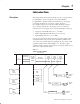
1 Chapter Description The Stepper Motor Positioning Assembly (cat. no. 1771-QA) allows programmable control of stepper motors by Allen-Bradley programmable controllers. Data and commands set to the stepper positioning assembly are converted to a pulse output for a user-supplied stepper motor translator which in turn provides the proper voltage and current to the stepper motor to produce the desired motion.
1–2 Introduction Stepper motor positioning assemblies can be used in applications requiring more than three axes by using additional I/O chassis. The stepper assemblies can be distributed throughout the plant using remote I/O or data highway configurations. Typically, each axis can control a linear slide although not limited to that type of mechanical load. The axes can be controlled independently or control of the axes can be synchronized.
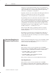
Introduction 1–3 For specific information required by EN 61131-2, see the appropriate sections in this publication, as well as “Industrial Automation Wiring and Grounding Guidelines For Noise Immunity,” Allen-Bradley publication 1770-4.1 Open style devices must be provided with environmental and safety protection by proper mounting in enclosures designed for specific application conditions.
1–4 Introduction Publication 1771-UM002A–EN–P – May 2000
Chapter 2 Assembly and Installation General The stepper positioning assembly can be wired for 1-axis operation with a stepper translator and motor as shown in Figure 2.1. One stepper controller module can control up to three pulse output expander modules installed in the same chassis. When the application calls for 2-or 3-axis control, each additional expander module should be wired as shown in Figure 2.1. No more than one stepper controller module can operate in an I/O chassis. Figure 2.
2–2 Assembly and Installation Input switch contacts should be compatible with the voltage and current levels of the input circuits. The pulse output expander module will accept inputs from open collector logic devices or grounded switch contacts, and inputs from the Allen-Bradley Encoder/Counter Module (cat. no. 1771-IJ, -IK). Refer to section titled “Module Specifications” for additional input specifications.
Assembly and Installation 2–3 Stepper Translator and Power Supply The stepper translator and power supply convert digital information from the pulse output expander module into the proper voltage and current for the precise control of a stepper motor. For compatibility with the pulse output expander module, the translator must accept low true logic. The programmed maximum pulse rate from the pulse output expander module to the translator can be any value up to 20,000 pulses per second.
2–4 Assembly and Installation Table 2.A Summary of Internal Switch Functions Switch Assembly Function Description 1 Output Format Separate forward and reverse pulse outputs, or Pulse out, direction output 2 Input Logic low = true or high = true 3 Expander Module Each expander module must have a different Address binary address, either 1, 2 ,or 3. 4, 5, 6 Module Output Push-Pull or Current Source (open emitter), or Current Sink (open collector). Figure 2.
Assembly and Installation 2–5 4. Set the switches as described in the following sections. Some switches are labeled on/off. Others may be labeled open for the off position. 5. Reassemble the module. Start all four screws before tightening to facilitate alignment of the covers and printed circuit board. Output Format (S1) The output format that determines forward or reverse motion differs between translators.
2–6 Assembly and Installation Other translators are designed to receive only one pulse train at a single “pulse” terminal. These translators usually have a separate terminal for direction information. If a high (or low) signal is sent to the “direction” terminal, the stepping motor rotates in the reverse direction. If a low (or high) signal is sent to this terminal, the stepping motor rotates in the forward direction.
Assembly and Installation 2–7 Table 2.D Expander Module Address (S3) Switch Assembly S3 Expander Switch 1 Switch 2 Switch 3 Address ON OFF OFF 1 OFF ON OFF 2 ON ON OFF 3 Expander Module Output (S4, S5, S6) The choice of pulse output expander module output, either push-pull, current source (open emitter) or current sink (open collector), is user-selectable to best match the input characteristics of the stepper translator.
2–8 Assembly and Installation ! ATTENTION: Avoid shorting any of the output terminals to ground, to the common terminal, or to the positive (+) terminal of a power supply. Damage to the module could occur. The settings of switch assemblies S4, S5 and S6 for the desired module output are summarized in Table 2.E. Set all switch positions in assemblies S4, S5 and S6 to the same output configuration. Table 2.
Assembly and Installation 2–9 • EXPANDER COMMUNICATIONS FAULT (Red) This indicator is normally off. If a communications fault between the stepper controller module and any one of the pulse output expander modules is detected, or a hardware fault in any one of the pulse output expander modules is detected, this indicator will illuminate. Important: If both red indicators illuminate simultaneously at power-up, the stepper controller module has a hardware fault.
2–10 Assembly and Installation System Grounding Considerations The following should be connected to earth ground: • Ground prong of all AC line cords • Negative (-) or common terminal of the I/O power supply(ies) • One I/O chassis mounting stud Ground the drain wire of the cable connecting the pulse output expander module to the stepper translator. This cable should be grounded either at the translator or at the I/O chassis, but not both. See Shield Connection below.
Assembly and Installation 2–11 The module is slotted in two places on its rear edge. The position of the keying bands on the backplane connector must correspond to the slots to allow insertion of the module so that only the desired module will fit in this slot. Refer to Figure 2.4.
2–12 Assembly and Installation Publication 1771-UM002A–EN–P – May 2000
Chapter 3 Programming and Operation General The desired motion of the stepper motor can be accelerated, decelerated or maintained at constant rate by controlling the pulse rate from the pulse output expander module. Motion can be rotational such as used to position an indexing table, or can be linear such as obtained when a linear slide is driven forward or backward by turning a threaded shaft. In either case, the position at any given moment is defined by the number of pulses sent to the stepper motor.
3–2 Programming and Operation Move Definition A move in its simplest form consists of an acceleration of the stepper motor axis, a final rate, a deceleration to zero and a final position (Figure 3.1). The value for an acceleration is the time required to achieve a final rate. Values can be chosen from 0-9.99 seconds. The final rate determines the constant speed of machine motion. The final rate value can vary from 1 to 20,000 pulses per second. The decel value, any value from 0-9.
Programming and Operation 3–3 In any mode, when the working moveset is finished, the storage moveset automatically becomes the next working moveset. Then another (storage) moveset can be block transferred to the stepper positioning assembly. In the continuous and independent modes of operation, the storage moveset must be received by the stepper controller module before the third from last move of the working moveset is complete (for example, move 8 of 10 moves).
3–4 Programming and Operation Jog A jog allows an axis to be manually controlled by an operator independent of other axes in the system. This can be done at any time except when a positioning profile is in progress. A jog can be initiated by a hardware or software input to the stepper positioning assembly. Jog data is one move block that controls one axis. The job move block typically is contained in a separate 1-move (10-word) moveset.
Programming and Operation 3–5 Continuous Mode The continuous mode allows moves of the moveset to be blended continuously into a move profile with fully programmed accelerations and decelerations. One start command is required for the entire positioning profile. A done bit is set at completion. Each move is defined as having a ramp, a final rate and a final position. The last move of the profile, in addition to the ramp, final rate and final position, contains a deceleration to zero (Figure 3.3).
3–6 Programming and Operation A done bit is set for each axis at completion of each positioning profile. If all axes (up to three) are not synchronized, then the control of any axis is completely independent of the other(s). Three different single-axis machines could be controlled by one stepper controller module and three pulse output expander modules in one I/O chassis. Independent Mode The independent mode allows a chain of single-step moves to be sequentially executed.
Programming and Operation 3–7 When using the independent mode and the axes are synchronized, all but the last axis to finish the move in process will stop motion when finished and wait for the last axis to complete its move. All axes will then begin the next move simultaneously as soon as the last axis has finished its move. The process then repeats for each move in the positioning profile (Figure 3.5). Figure 3.
3–8 Programming and Operation Data Block Concepts Words that control the motion of the stepper motor axis, record position or monitor move diagnostics are stored in data table files. These words are grouped into the following three kinds of data blocks. • Moveset Block • Move Block • Status Block In addition to move data, the blocks contain special control or status words.
Programming and Operation 3–9 Moveset Control Word A moveset block must contain a moveset control word as the first word in the block. Each of the bits of the moveset control word serves a function in the control of a stepper motor axis. Bit functions of the moveset control word are defined below and summarized in Figure 3.7. Figure 3.
3–10 Programming and Operation Bit 03 Synchronized Axes Bit. If this bit is set for any axis, it must be set for the other axes so that all (two or three) axes controlled by the stepper positioning assembly are synchronized. Synchronized axes must be operating in the same positioning mode. (Bits 01, 02, and 03 must be set identically in the moveset control words of the synchronized axes.) Refer to “Synchronization of Axes.” Bit 04 Reset Command Bit.
Programming and Operation 3–11 When the decel/instantaneous bit is zero, output pulses will cease instantly when a software stop command is received. A hardware stop input in instantaneous, independent of the decal/instantaneous bit. This bit is generally set when a stop bit is set. Bits 10, 11 Axis Address Bits. These bits define the axis to be controlled by the data and/or commands in the moveset block.
3–12 Programming and Operation The load jog command bit (bit 03 of the single move control word, defined in section titled “Move Block”) must be set to identify jog move block data. The user program should clear the software jog reverse command bit and allow the stepper controller module time to see the bit cleared before another jog to that axis is enabled. Bit 15 Software Jog Forward Command Bit. Same as bit 14. See software jog reverse command bit. Bit 16 Moveset Bit.
Programming and Operation 3–13 Avoid sending multiple commands to the stepper controller module at the same time. A programming error could result or the data/command could be ignored. All bits must be set carefully to tailor the move profile(s) to the application requirements and to avoid illegal bit combinations. If only one command is transferred at a time with proper handshaking, no difficulty should be encountered.
3–14 Programming and Operation Figure 3.9 Offset and Preset Words Data Table 17 10 07 00 MCW 0 = Add 1 = Subtract 0 1 = Assert Initialization Preset 0 0 = Move Preset 7 9 9 9 Offset 1 0 0 0 9 9 9 MS Preset 0 0 0 9 9 9 LS Preset 1 0 10522 The moves affected by the offset will be those stored in the working and storage moveset when the command is received.
Programming and Operation 3–15 Initialization Preset Typically it may be necessary to jog the machine to a starting position before the positioning profile(s) is (are) started. The position register of the stepper controller module will read some number of position pulses representing the machine starting position. The initialization preset can be used to reset the value of the position register to zero, or to any value that would be used as the profile starting value.
3–16 Programming and Operation Move Preset The move preset can be used to adjust the starting point value of any move in a moveset whenever necessary. For example, the move preset can extend one or more moves of the profile beyond the 999,999 pulse limit of the stepper controller module. The move preset is enabled by bit 00 in the single move control word (see section titled “Move Block”).
Programming and Operation 3–17 Move Block A move block contains ramp, final rate, final position and deceleration data that characterize a move. A moveset block must contain from 1 to 10 move blocks. A move block contains the following words (Figure 3.12): • Single Move Control Word • Move Data Figure 3.
3–18 Programming and Operation Bit 02 Skip Bit. The skip bit allows one or more moves of a moveset to be ignored without reprogramming. When this bit is set, the corresponding move block is skipped over. When operating in the continuous mode, the move preceding the skipped move and the move following the skipped move are blended automatically. Refer to section titled “Application Considerations” to ensure that the blend is achievable without a programming error.
Programming and Operation 3–19 Move Data Move data is contained in the remaining five words of the move block (Figure 3.13). Values are entered in BCD. Those shown in Figure 3.13 are the maximum allowable values. Undefined bits (bits 14-17) in the words specifying the ramp, decel and position must be filled with zeros. Figure 3.13 Move Block Data Table 17 10 07 Single Move Control Word SMCW Ramp 00 0 0 0 0 9 Rate 9 9 9 0 – 9.99 Seconds 9 9 9 0 – 9,999 x 1 0 – 2,000 x 10 0 – 9.
3–20 Programming and Operation In the continuous mode, the decel value is not used in the move profile except for the last move. However, the decel value has a special purpose in the continuous mode: it allows a controlled decel to 0Hz rate under two conditions: 1. If a system fault is detected, the move in progress will decel to a 0Hz rate (come to a stop) in the time defined by the decel value. 2.
Programming and Operation 3–21 The first word in the status block is reserved for future use (Figure 3.14). Each expander module then uses three words, the first of which is the status word. The remaining two are position words. The number of status and position words returned to the PC processor depends on the highest numbered axis in the stepper positioning assembly, not on the number of axes used.
3–22 Programming and Operation Figure 3.15 Status Word Status word 17 16 15 14 13 12 11 10 07 06 05 04 03 02 01 00 Done Command Verified Moveset Data Received Jog Forward Direction Rev/Fwd Jog Reverse System Fault Programming Error Move Number 1 – 10 (1-A Hex) Reset Program Stop Hardware Stop 10520 Status Word The bits in the status word allow the PC program to verify that move commands have been received and implemented.
Programming and Operation 3–23 Bit 03 System Fault Bit. This bit is set if a system failure such as a communication error is detected in the stepper positioning assembly, or invalid data is detected. The output decelerates to 0Hz at the programmed decel value when a system failure is detected. Bit 04 Programming Error Bit. This bit will be set for a number of error conditions including the following. • Illegal bit combinations exist in the data transferred to the stepper controller module.
3–24 Programming and Operation Bits 10-13 Move in Progress Bits. The bit pattern in Hex shows which move (1-10) of the moveset is currently being executed. (decimal 10=Hex A). Bit 14 Jog Reverse Bit. This bit is set when a software jog reverse command has been received or when a hardware jog reverse input is asserted. Bit 15 Jog Forward Bit. This bit is set when a software jog forward command has been received or when a hardware jog forward input is asserted.
Programming and Operation 3–25 The values shown in the figure are the maximum allowable values for position pulses. Bits 14, 15, 16 of the MS position word and the upper four bits of the LS position word are undefined. They will be read block transferred to the PC processor as zeros. Bit 17 of the MS position word is used to indicate a negative position. For example, a reverse jog to below zero will set bit 17. Bit 17 is zero for a position between 0 and 999,999 pulses.
3–26 Programming and Operation The data address of a block transfer instruction should be the first available address in the timer/counter accumulated area of the data table. This address is 0308 for the Mini-PLC-2/15 controller. For the PLC-2/30 controller, this address depends on the number of I/O racks connected to the processor module, i.e. address 0208 for one I/O rack, 0308 for two racks, etc. to 0708 for six racks and 2008 for seven racks.
Programming and Operation 3–27 Two consecutive data addresses must be used in bidirectional block transfer. Both contain the I/O rack address of the stepper controller module. For bidirectional operation, each data address word also contains an enable bit; bit 16 for a write operation and bit 17 for a read operation. When the PC processor searches the data addresses in the timer/counter accumulated area of the data table, it finds two consecutive data addresses both containing the same module address.
3–28 Programming and Operation Secondly, the block length can be changed alternately in accordance with the block lengths of the enabled instructions. The block length of the last enabled write block transfer instruction having a common module address will govern the number of words transferred. File Addresses Two files are required for bidirectional block transfer: one to receive data transferred from the module, the other temporarily holding data to be sent to the module.
Programming and Operation 3–29 Figure 3.17 Example Bidirectional Block Transfer Data Table 010 R W 1 1 Block length code ~ ~ 013 Output image table low byte 040 041 Data Addresses store the module address, rack 1, module group 3, slot 0. 113 Input image table low byte ~ ~ R W 1 1 1 3 0 1 3 0 R W 1 1 ~ ~ ~ ~ 2 0 0 140 3 0 0 141 ~ ~ ~ ~ Block Transfer Read File 10 Words, Max. Addresses Available for Storage 200 211 212 277 300 Block Transfer Write File 64 Words, Max.
3–30 Programming and Operation Programming Considerations This section describes how block transfer concepts can be applied to programming the stepper positioning assembly. It is assumed that an Industrial Terminal (cat. no. 1770-T3) will be used and that the programmable controller is either an Allen-Bradley Mini-PLC-2/15 or PLC-2/30.
Programming and Operation 3–31 When the block length of the read block transfer instruction is set to the default value, 00, the stepper controller module will automatically establish the default number of status words to be transferred; either four, seven or ten words. This number is determined by the highest address of a pulse output expander module contained in the chassis.
3–32 Programming and Operation B. Setting the skip bit in the single move control words corresponding to unwanted move blocks. Program logic can be used to set bit 02 in the 59th, 53rd, 47th word, etc. of the write block transfer file so that respectively the last, next to last, third from last, etc. move blocks of a moveset are skipped by the stepper controller module. C. Programming the block transfers of multiple movesets so that each moveset is the same size or larger than the previous one.
Programming and Operation 3–33 Jog reverse and Jog forward MCW, bits 14 and 15 When either software jog command bit 14 or 15 is enabled in the user program, the jog move will be executed if jog data had been previously transferred. The software jog command can be transferred to the stepper controller module with jog moveset data (1 move) or can be transferred by transferring only a moveset control word with bit 14 or 15 set.
3–34 Programming and Operation • 1 write block transfer file - 64 words for the temporary storage of data to be write block transferred. • 1 read block transfer (buffer) file - When the block transfer read instruction is set to default, 00, this file uses four words for axis 1, seven words for axis 2 or ten words for axis 3. The balance of this file can store other data because the balance is not used by the read block transfer instruction.
Programming and Operation Important: 3–35 Increasing the size of the data table by 128-word sections reduces the amount of words for user program by the same amount. Handshaking Handshaking is the exchange of commands and/or data with status information between the PC processor and stepper controller module. Handshaking is normally used to ensure successful block transfers independent of data transfer times.
3–36 Programming and Operation The command verify (status) bit will be reset whenever: A. the stepper controller module receives a transfer where none of the following command bits are set: start (bit 00), stop (bit 06), offset (bit 13), jog (bit 14 or 15), override (bit 17), initialization preset (MS preset, bit 17), and load jog (SMCW, Bit 03), or B. a reset command (bit 04) is received.
Programming and Operation 3–37 Table 3.
3–38 Programming and Operation The method for calculating the worst case time between block transfers will be covered for the following cases: PLC-2/30 remote and local systems, and Mini-PLC-2/15 controller. PLC-2/30 (PLC-2/20) Remote System The system scan time for a remote PLC-2/30 or PLC-2/20 system is the sum of the processor scan time, the processor I/O scan time (between processor and remote distribution panel), and the remote distribution panel I/O scan time.
Programming and Operation 3–39 Example Problem 1 A PLC-2/30 programmable controller is controlling 4 I/O racks in remote configuration (Figure 3.18). A 3-axis stepper positioning assembly is located in each rack. Assume that the stepper controller module is operating in default mode and that the ladder diagram program contains 4K words (K 1024). There are no other block transfer modules in the system. Figure 3.
3–40 Programming and Operation Processor Scan Time PS = (5ms/lK words x (4K words) = 20ms Processor I/O Scan Time PIO = (0.5 ms/rack number) x (4 rack numbers) = 2 ms Remote Distribution I/O Scan Time RIO = (7 ms/chassis) x (4 chassis) = 28ms Number of Words Transferred = 64 (write) or 10 (read) 3. Calculate the block transfer times, TW for a write and TR for a read operation. TW = PS + PIO + 2(RIO) + .5W + 13 TW = 20 + 2 + 2(28) + .5(64) +13 TW = 123ms (write) TR = PS + PIO + 2(RIO) + .
Programming and Operation 3–41 3. Calculate the block transfer time T for the read and write operation. T = 0.1ms + (.075ms/word x number of words transferred) The same equation is used for either read or write transfer times. 4. Calculate the worst case system time ST between transfers. ST = PS + PIO + T(1) + T(2) + T(3) +... Example Problem 2 A PLC-2/30 programmable controller is controlling four I/O racks in a local configuration (Figure 3.19).
3–42 Programming and Operation Processor Scan Time PS = (5ms/lK words) x (4K words) = 20ms. Processor I/O Scan Time PIO = (0.5ms/rack number x (4 rack numbers) = 2ms Number of Words Transferred = 64 (write) or 10 (read) 3. Calculate the block transfer times T for the write and read operation. T = 0.1 + (.075ms/word x 64 words) = 0.1 + 4.8 = 4.9ms (write) T = 0.1 + (.075ms/word x 10 words) = 0.1 + .75 = .85ms (read) 4. Calculate the worst case system time ST between 2 consecutive write block transfers.
Programming and Operation 3–43 T = 0.1ms + (.16ms/word x number of words transferred) The same equation is used for either read or write transfer times. 3. Calculate the worst case system time ST between transfers. ST = PS + T(1) + T(2) + T(3) + ... Example Problem 3 A Mini-PLC-2/15 programmable controller is controlling one 3-axis stepper controller assembly in its I/O rack. The ladder diagram program contains 2K words. Otherwise, this example problem is identical to example problem 1. Solution 1.
3–44 Programming and Operation Application Considerations The values which can be selected for ramp and decel times, the final rate, and final position allow a very wide variety of move profiles to be programmed. However there are some constraints which, if not taken into consideration, can result in a programming error when the move profile is executed. These constraints, for the most part, should be considered when programming long acceleration times with brief but relatively high final rates.
Programming and Operation 3–45 The following three examples show how this equation can be used. Example Problem 1: Single-step mode or independent mode. For the next move of a move profile, the change in move position from beginning to end (DELPOS) must be 26k pulses. Determine the maximum allowable final rate (FR) when using equal ramp and decel times of 4 seconds. The parameters of the equation (IR, FR, RT and DELPOS) and a sketch of the move are shown in Figure 3.20. Figure 3.
3–46 Programming and Operation 4(10k + 0) 4 + 10k 2 + 0.02 < 26k 2 20k + 20.2k <26k 40.2k <26k This exceeds the constraint. The selected value of 10k was too large. Try FR = 6k. 4(6k + 0) + 6k 2 12K + 12.12K <26k 4 + 0.02 < 26k 2 24.12k <26k This is within the constraint. The final rate of 6k pulses per second is allowable and can be used. Any value greater than approximately 6.4k pulses would cause a programming error when the move is executed.
Programming and Operation 3–47 RT = 3 seconds FR = 10k pulses per second IR = 2k pulses per second (final rate of previous move) DT = 0 (decel time is zero in all moves except the last in the continuous mode, by definition) Find DELPOS, then add this figure to the final position of the previous move (100K) to determine the minimum final position that can be programmed for the move. 3(10k + 2k) 0 + 0.02 < 26k + 10k 2 2 18k + 0.2K
3–48 Programming and Operation The parameters of the equation (IR, FR, RT and DELPOS) and a sketch of the move are shown in Figure 3.22. Figure 3.22 Last Move in a Continuous Mode Rate IR 20 ms FR Position DT RT DEL POS Final Position Start Position 10531 Solution: Write down the known facts. RT = 6 seconds IR = 12k pulses per second (final rate of previous move) FR = 6k pulses per second DELPOS = 62k pulses (742k pulses - 680k pulses) 6(6k + 12k) 2 54k + 6k + 6k DT + 0.02 < 62k 2 DT + 0.
Programming and Operation 3–49 Decel and Position Considerations for a 0Hz Rate Move A 0Hz rate move must be used when the profile is brought to a stop such as when reversing direction. When programming a 0Hz rate move, the ramp time and decel time are not used by the stepper controller module regardless of whether or not they are programmed. Only the rate (0Hz) and final position values are entered.
3–50 Programming and Operation The parameters of the equation (DELPOS, T and IR) and a sketch of the move are shown in Figure 3.23. Figure 3.23 0Hz Rate Move Rate 20 ms IR Position T DEL POS Start Position Final Position 10533 Example Problem 1: The seventh move of a profile in continuous mode must be brought to 0Hz rate so that the profile can return to its starting point value. The final rate and final position of the previous move are 16k pulses per second and 510k pulses, respectively.
Programming and Operation 3–51 This exceeds 9.99 seconds. Either the position of the 0Hz rate move must be decreased, or the final rate of the previous move must be raised, or the final position of the previous move must be extended (or a combination of all three) in order to bring the decel time to 9.99 seconds or less. Assume that the DELPOS can be changed. If the DELPOS is reduced from 110k to 80k pulses, the actual decel time will be 10 - 0.04 = 9.96 seconds (from line 2) and within limits.
3–52 Programming and Operation If ORTProg in equation 3a is zero, then ORTAct will be instantaneous (<10ms). The equation parameters (ORTAct, ORTProg, OFR, and IR) and a sketch of the move are shown in Figure 3.24. Example Problem 1: An override ramp time is programmed for 6.2 seconds. What will be the actual override ramp time if the override is enabled while a rate (IR) of 8k pulses per second is being executed? The final rate of the override move is 10k. Solution: Write down the known facts.
Programming and Operation 3–53 Figure 3.24 Override Ramp Time Rate ORT Prog ORT Act OFR Executed Profile IR Not Executed Position Override Move Move in Progress A) Override Ramp Time, OFR > IR Rate ORT Act Must Not Exceed 9.99 Seconds IR Slope of executed override ramp will be equal but opposite to that of programmed override ramp.
3–54 Programming and Operation Stepper Motor Acceleration Considerations The stepper motor specifications will contain an acceleration limitation. It will state some maximum acceptable acceleration under load (change in pulse rate for a given duration, i.e. Hz/second). This motor acceleration constraint must be satisfied and should be considered especially when programming rapid accelerations to high final rates. The following equation can be used for a move that ramps from a 0Hz rate to a final rate.
Programming and Operation 3–55 If the resonant frequency is encountered, its effect can be dampened or eliminated as follows: • If encountered in a steady state condition (at or near a chosen final rate), increase the inertial load or change the final rate. • If encountered when accelerating or decelerating through the resonant frequency, increase the rate of acceleration or deceleration by programming shorter ramp or decel times.
3–56 Programming and Operation Minimum Move Time A minimum “move in progress” time is required by the stepper controller module to process the next move of a sequence, and to evaluate and act on incoming commands. Every move sent from the stepper controller module to a pulse output expander module must have a duration long enough to allow the stepper controller module to service the remaining expander modules, process any new commands and return to the original expander module before the move has ended.
Chapter 4 Example Programs General Two example programs are presented in this chapter. The purpose of these programs is to illustrate the procedure and documentation that should be used and to explain the relationship between the ladder diagram program, positioning profile(s) and move data. 1-Axis Program The ladder diagram program presented in this section is written for a 1-axis machine application having a positioning profile of 10 moves.
4–2 Example Programs Programming a 1-Axis Profile The task of programming can be simplified by documenting the desired positioning profile in the following manner. 1. Sketch the positioning profile and designate the ramp time, final rate, final position, and decel values as needed (Figure 4.1). Decide which of the three operating modes (continuous, independent or single step) should be used. Figure 4.1 Example 1-Axis Profile (Continuous Mode) Moves 2–8 RT=1.
Example Programs 4–3 Figure 4.2 Example 1-Axis Profile Moveset ALLEN-BRADLEY Programmable Controller Moveset Data (October, 1982) HEXIDECIMAL DATA MONITOR FILE–TO–FILE MOVE Counter Addr: 033 Axis No.: File A: 400 Moveset No.
4–4 Example Programs Figure 4.3 Example Jog Moveset with Preset Data ALLEN-BRADLEY Programmable Controller Moveset Data (October, 1982) HEXIDECIMAL DATA MONITOR FILE–TO–FILE MOVE Counter Addr: 032 Axis No.: 1 File Length: File A: 310 Moveset No.
Example Programs 4–5 Figure 4.
4–6 Example Programs 112 Jog and Preset Data 12 00 110 16 112 FILE TO FILE MOVE COUNTER ADDR: 0036 POSITION: 001 FILE LENGTH: 010 FILE A: 0310 – 0321 FILE R: 0500 – 0511 RATE PER SCAN 010 0036 EN 17 0036 DN 15 01 110 Profile Data 13 14 114 FILE TO FILE MOVE COUNTER ADDR: 0033 POSITION: 001 FILE LENGTH: 064 FILE A: 0400 – 0477 FILE R: 0500 – 0577 RATE PER SCAN 064 BLOCK XFER READ 0030 DATA ADDR: 140 MODULE ADDR: 00 BLOCK LENGTH: 0200 – 0277 FILE: 14 07 0033 EN 17 0033 DN 15 014 EN 07 114 DN 07
Example Programs 4–7 Figure 4.
4–8 Example Programs Position File A Data 029 C000 C000 030 0100 0100 031 0800 0800 032 0100 0100 033 0016 0016 034 0500 0500 035 C000 C000 036 0100 0100 037 0200 0200 038 0100 0100 039 0017 0017 040 0500 0500 041 C000 C000 042 0100 0100 043 0100 0100 044 0100 0100 045 0018 0018 046 0500 0500 047 C000 C000 048 0100 0100 049 0050 0050 050 0100 0100 051 0019 0019 052 0000 0000 053 C000 C000 054 0000 0000 055 0000 0000 056 01
Example Programs 4–9 Preset and Jog Data Preset and jog data are programmed in a 10-word moveset. The moveset data is contained in words 310-321 of the file-to-file move instruction having counter address 0036 as shown in rung 12 (Figure 4.4). The preset and jog data have been logged on the Moveset Data form (Figure 4.3). The function of the data is summarized in Table 4.A.
4–10 Example Programs Move Data The 10-move 1-axis positioning profile (Figure 4.1) is in the continuous mode, reverses direction at 19,200 pulses and returns to the starting position. In order to reverse direction in this mode, a 0Hz rate move must be programmed (move 9). Note that decel values for all moves except the last move are ignored by the stepper controller module unless a software controlled stop is initiated, or a system fault is detected.
Example Programs Position Number 1 Equivalent Word2 Word Description 4–11 Function 055 466 Final Rate zero (ignored by stepper controller module). 056 467 Decel Time 1.0 seconds (only used if needed for controlled stop). 057 - 058 470 - 471 Final Position 19,200 pulses. The position where the final rate is zero. 059 472 SMCW C000 hex. This begins the return move, move 10. 060 473 Ramp Time 2.
4–12 Example Programs Rungs 6 and 7 These rungs start and stop a jog forward move. When bit 112/00 is true, bit 310/15 (moveset control word, jog forward bit) is true and a jog forward is initiated. When bit 112/01 is false, the jog forward bit (bit 500/15) will be unlatched and jog motion will cease. Rungs 8 and 9 These rungs start and stop a jog reverse move. When bit 112/01 is true, bit 310/14 (moveset control word, jog reverse bit) is true and a jog reverse is initiated.
Example Programs 4–13 Rung 14 This rung contains the block transfer read instruction that receives status from the stepper controller module in rack 1, module group 4, slot 0. The block length is selected as 00 (default value). As such, the maximum number of words that the stepper controller module will transfer to the PC processor will depend on the highest address of the pulse output expander module(s) in the chassis: Ten for address 3, seven for address 2 or four for address 1.
4–14 Example Programs Commands are transferred to the stepper controller module by setting a bit in either the moveset control word, single move control word or MS preset word. The command bit can be set when the control word is in either of two locations: in file A of file-to-file move instructions FFM 0036 or FFM 0033, or in the write block transfer file R (500-577) where data resides momentarily when transferred to the stepper controller module. When programming a 1-axis profile, either can be used.
Example Programs 3-Axis Program 4–15 The ladder diagram program presented in this section is written for a 3-axis machine operation where each axis has a different 20-move continuous mode positioning profile. Sketches of the three profiles are shown in Figure 4.6. A detailed profile for each axis is shown in Figure 4.7, Figure 4.8 and Figure 4.9. The 3-axis system requires that one Stepper Controller Module (cat. no. 1771-M1) and three Pulse Output Expander Modules (cat. no.
4–16 Example Programs Figure 4.7 Axis 1 of Example 3-Axis Profile FR=1000 P/Sec Rate RT= 1.0 Sec FR=850 P/Sec FR=950 P/Sec FR=650 P/Sec FR=700 P/Sec FR=600 P/Sec FR=800 P/Sec FR=900 P/Sec Moves 2–18 RT=1.0 Sec FR=750 P/Sec FR=500 P/Sec FR=550 P/Sec Forward FR=450 P/Sec 1 FR=400 P/Sec FR=350 P/Sec 2 3 4 5 6 7 8 9 10 11 12 13 FR=300 P/Sec FR=250 P/Sec FR=150 P/Sec 14 15 16 1 17 18 0 Reverse 1500 4000 5000 6500 19000 20000 22000 RT=3.
Example Programs 4–17 Figure 4.8 Axis 2 of Example 3-Axis Profile FR=500 P/Sec Rate RT=1.0 Sec FR=350 P/Sec FR=300 P/Sec FR=450 P/Sec FR=400 P/Sec Moves 2–18 RT=1.0 Sec FR=45 P/S FR=200 P/Sec FR=150 P/Sec FR=250 P/Sec FR=40 P/S FR=100 P/Sec FR=35 P/S Forward FR=50 P/S FR=25 P/S FR=30 P/S FR=20 P/S 1 2 FR=15 P/S 3 4 5 6 7 8 9 10 11 12 13 14 15 16 17 18 0 Reverse 1000 1800 2500 3200 3900 4500 5400 5000 5900 5700 6200 6100 6400 6300 DT=2.
4–18 Example Programs Figure 4.9 Axis 3 of Example 3-Axis Profile FR=1000 P/S Moves 2–18 RT=1.0 Sec FR=500 P/S FR=900 P/S RT= 2.
Example Programs 4–19 Also note that command bits for each axis are set in the corresponding control word in file A of the file-to-file move instruction prior to transfer to the stepper controller module. Command bits are not set in the write block transfer file, file R, as can be done in a 1-axis program. Each axis is programmed for 20 moves. Therefore two 10-move 64 word profile movesets must be programmed for each axis.
4–20 Example Programs Figure 4.
Example Programs 112 110 112 Unlatch Jog Forward Axis 2 15 04 15 11 112 Jog Reverse Axis 2 16 05 112 112 112 Unlatch Jog Reverse Axis 2 17 05 110 00 12 Offset Axis 2 4–21 300 U OFF 15 224 14 300 U OFF 14 224 18 13 03 112 Stop Axis 3 19 236 06 06 112 Stop Axis 3 236 20 07 06 112 Reset Axis 3 236 21 07 04 110 Initialize Preset Axis 3 240 22 17 05 112 Jog Forward Axis 3 236 23 15 11 112 112 110 Unlatch Jog Forward Axis 3 24 11 04 15 112 Jog Reverse Axis 3 300 U
4–22 Example Programs 110 28 16 110 Command File (Includes Offset and Preset Data) Axis 1 17 110 FILE TO FILE MOVE COUNTER ADDR: 0035 POSITION: 001 FILE LENGTH: 004 FILE A: 0212 – 0215 FILE R: 0300 – 0303 RATE PER SCAN 004 0035 EN 17 0035 DN 15 07 110 04 112 Command File (Includes Offset and Preset Data) 02 112 Axis 2 29 03 110 FILE TO FILE MOVE COUNTER ADDR: 0036 POSITION: 001 FILE LENGTH: 004 FILE A: 0224 – 0227 FILE R: 0300 – 0303 RATE PER SCAN 004 0036 EN 17 0036 DN 15 06 110 03 112 30 06
Example Programs 112 Jog Data Axis 2 32 04 112 05 FILE TO FILE MOVE COUNTER ADDR: 0040 POSITION: 001 FILE LENGTH: 010 FILE A: 0224 – 0235 FILE R: 0300 – 0311 RATE PER SCAN 010 4–23 0040 EN 17 0040 DN 15 112 Jog Data Axis 3 33 11 112 12 FILE TO FILE MOVE COUNTER ADDR: 0043 POSITION: 001 FILE LENGTH: 010 FILE A: 0236 – 0247 FILE R: 0300 – 0311 RATE PER SCAN 010 0043 EN 17 0043 DN 15 110 34 Moveset 1 (Axis 1) 14 FILE TO FILE MOVE COUNTER ADDR: 0033 POSITION: 001 FILE LENGTH: 064 FILE A: 0400 – 0
4–24 Example Programs 201 37 Moveset 0 (Axis 1) 16 FILE TO FILE MOVE COUNTER ADDR: 0034 POSITION: 001 FILE LENGTH: 064 FILE A: 0500 – 0577 FILE R: 0300 – 0377 RATE PER SCAN 064 0034 EN 17 0034 DN 15 204 38 Moveset 0 (Axis 2) 16 FILE TO FILE MOVE COUNTER ADDR: 0042 POSITION: 001 FILE LENGTH: 064 FILE A: 0700 – 0777 FILE R: 0300 – 0377 RATE PER SCAN 064 0042 EN 17 0042 DN 15 207 39 Moveset 0 (Axis 3) 16 FILE TO FILE MOVE COUNTER ADDR: 0045 POSITION: 001 FILE LENGTH: 064 FILE A: 1100 – 1177 FILE
Example Programs Block Transfer Time–Out 114 43 06 046 0046 TON 0.
4–26 Example Programs Figure 4.11 Example Command File, Axis 1 ALLEN-BRADLEY Programmable Controller Moveset Data (October, 1982) HEXIDECIMAL DATA MONITOR FILE–TO–FILE MOVE Counter Addr: 035 File A: 212 to 215 Position 1 2 3 4 5 FILE A DATA 0 0 0 0 1 1 0 2 0 0 0 0 File Length: 04 File R: 300 to 303 Moveset No.: Description 0 0 0 0 1 Axis No.: Move Position FILE A DATA 33 34 35 36 37 MCW Offset MS Preset LS Preset SMCW Description Move MS Pos LS Pos SMCW Ramp Rate 10606 Figure 4.
Example Programs 4–27 Figure 4.13 Example Command File, Axis 3 ALLEN-BRADLEY Programmable Controller Moveset Data (October, 1982) HEXIDECIMAL DATA MONITOR FILE–TO–FILE MOVE Counter Addr: 037 File A: 236 to 241 Position 1 2 3 4 5 FILE A DATA 0 0 0 0 3 3 0 1 0 0 0 5 File Length: 04 File R: 300 to 303 Moveset No.: Description 0 0 0 0 3 Axis No.: Move Position FILE A DATA Description 33 34 35 36 37 MCW Offset MS Preset LS Preset SMCW Move MS Pos LS Pos SMCW Ramp Rate 10608 Figure 4.
4–28 Example Programs Figure 4.15 Example Jog Moveset, Axis 2 ALLEN-BRADLEY Programmable Controller Moveset Data (October, 1982) HEXIDECIMAL DATA MONITOR FILE–TO–FILE MOVE Counter Addr: 040 Axis No.: File A: 224 Moveset No.
Example Programs 4–29 Figure 4.16 Example Jog Moveset, Axis 3 ALLEN-BRADLEY Programmable Controller Moveset Data (October, 1982) HEXIDECIMAL DATA MONITOR FILE–TO–FILE MOVE Counter Addr: 043 Axis No.: File A: 236 Moveset No.
4–30 Example Programs Figure 4.17 Example Profile Moveset, 1 Axis 1 ALLEN-BRADLEY Programmable Controller Moveset Data (October, 1982) HEXIDECIMAL DATA MONITOR FILE–TO–FILE MOVE Counter Addr: 033 Axis No.: File A: 400 Moveset No.
Example Programs 4–31 Figure 4.18 Example Profile Moveset 0 Axis 0 ALLEN-BRADLEY Programmable Controller Moveset Data (October, 1982) HEXIDECIMAL DATA MONITOR FILE–TO–FILE MOVE Counter Addr: 034 Axis No.: File A: 500 Moveset No.
4–32 Example Programs Figure 4.19 Example Profile Moveset 1, Axis 2 ALLEN-BRADLEY Programmable Controller Moveset Data (October, 1982) HEXIDECIMAL DATA MONITOR FILE–TO–FILE MOVE Counter Addr: 041 Axis No.: File A: 600 Moveset No.
Example Programs 4–33 Figure 4.20 Example Profile Moveset O, Axis 2 ALLEN-BRADLEY Programmable Controller Moveset Data (October, 1982) HEXIDECIMAL DATA MONITOR FILE–TO–FILE MOVE Counter Addr: 042 Axis No.: File A: 700 Moveset No.
4–34 Example Programs Figure 4.21 Example Profile Moveset 1, Axis 3 ALLEN-BRADLEY Programmable Controller Moveset Data (October, 1982) HEXIDECIMAL DATA MONITOR FILE–TO–FILE MOVE Counter Addr: 044 3 Axis No.: File Length: File A: 1000 to 1077 Moveset No.
Example Programs 4–35 Figure 4.22 Example Profile Moveset 0 Axis 3 ALLEN-BRADLEY Programmable Controller Moveset Data (October, 1982) HEXIDECIMAL DATA MONITOR FILE–TO–FILE MOVE Counter Addr: 045 3 Axis No.: File Length: File A: 1100 to 1177 Moveset No.
4–36 Example Programs Rungs 1 and 2 Controlled stop rungs for axis 1. When user input 110/16 is energized, bit 221/06 (MCW, stop bit) and 212/07 (MCW, decl/inst bit) are high and the contents of the file-to-file move instruction in rung 28 are transferred to the stepper controller module. The stepper controller module will perform a controlled stop using the decel value in the move being processed at the time the stop command is received. Rung 3 Reset rung for axis 1.
Example Programs 4–37 Rung 9 Offset rung for axis 1. When user input 110/04 is energized, bit 212/13 (MCW, offset bit) is true and the number of pulses programmed in offset word 213 (file-to-file move instruction, rung 28) will be added or subtracted to the final position of each move according to the state of bit 213/17 (subtract/add offset bit). Refer to Offset Word in chapter 3. Rungs 10 thru 27 Stop, reset, initialization preset, jog forward, jog reverse and offset rungs for axis 2 and axis 3.
4–38 Example Programs Rung 37 When the first profile moveset is sent to the stepper controller module (rung 24), bit 16 of status word 201 will toggle. When bit 201/16 toggles, a false-to-true transition in rung 37 occurs and the second profile moveset is transferred to the stepper controller module and is stored in the buffer associated with that axis. The second profile moveset (moves 11-20) for axis 1 is stored in file A (500-577).
Example Programs 4–39 Rungs 45 thru 47 These rungs display the status of axes 1, 2, and 3. Word 150 is reserved for future use, word 151 is the status word for axis 1, word 152 is the MS position value for axis 1 and word 153 is the LS position value for axis 1. The relationship applies to words 154-156 (axis 2) and words 157-161 (axis 3). Operational Summary After the ladder diagram program has been written, the appropriate move data can be entered in the file-to-file move instructions in rungs 28-39.
4–40 Example Programs ALLEN-BRADLEY Programmable Controller Moveset Data (October, 1982) HEXIDECIMAL DATA MONITOR FILE–TO–FILE MOVE Counter Addr: File A: Position to FILE A DATA 1 2 3 4 5 6 7 8 9 10 11 12 13 14 15 16 17 18 19 20 21 22 23 24 25 26 27 28 29 30 31 32 Publication 1771-UM002A–EN–P – May 2000 Axis No.: File Length: Moveset No.
Example Programs ALLEN–BRADLEY Programmable Controller DATA TABLE WORD MAP (1024 WORD) (Publication 5044 – February, 1982) PROJECT NAME DESIGNER WORD ADDRESS 000 4–41 PAGE OF ADDRESS TO PROCESSOR DATA TABLE SIZE FROM––––––––––––––––––––––––––––––––– (32 WORDS) –––––––––––––––––––––––––––––––––––TO WORD ADDRESS REF.
4–42 Example Programs Publication 1771-UM002A–EN–P – May 2000
Chapter 5 Troubleshooting General A programming error will be reflected in the status word of the affected axis with the programming error bit set (bit 04). The systems fault bit in some cases will also be set. When the system fault bit is not set, programming errors can be cleared by transferring new error-free block transfer data of any length to that same axis.
5–2 Troubleshooting Table 5.A Power-Up Troubleshooting Led Indication F 1 2 Possible Cause Corrective Action PC COMM FAULT1 EXPANDER COMM FAULT1 ACTIVE1 MODULE FAULT2 Normal Operation None PC COMM FAULT EXPANDER COMM FAULT ACTIVE MODULE FAULT Expander address is incorrect. More than one 1771-M1 module in the chassis No 1771-OJ module in the chassis Switch 3 on 1771-OJ module must be 001, 010 or 011. Install only one 1771-M1 module per chassis. Install at least one 1771-OJ module per chassis.
Troubleshooting 5–3 Table 5.B Operation Troubleshooting Status Word Bits Programming Error, Bit 04 System Fault, Bit 03 Possible Cause 1 0 Single move control word of one or more move blocks (except in a truncated or ”zeroed” end portion of a moveset) does not have bits 17 and 16 = 1 or bits 15-04 = 0. Set or reset bits where required. Check moveset data for a missing or extra entry causing all other data to be shifted up or down.
5–4 Troubleshooting Programming Error, Bit 04 System Fault, Bit 03 Possible Cause Corrective Action 1 1 Override ramp not acceptable The actual executed ramp time of the first move of an override moveset is generally not the value programmed. Refer to override ramp time text and equations section titled “Decel and Position Considerations for a 0Hz Rate Move.” 1 1 Offset value, when added, causes a position value greater than 999,999 or, when subtracted, causes a position value less than 0.
Troubleshooting Illegal Bit Combinations 5–5 Certain combinations of bits or an illegal bit state entered in the moveset control word, single move control word and/or MX preset word can cause a programming error. Refer to Table 5.C. Table 5.C Illegal Bit Combinations 1 Init. Preset Rate Multiplier 17 Skip 03 02 01 00 Load Jog Identification 17 16 MS Preset Word Move Preset 17 16 15 14 13 12 11 10 07 06 05 04 03 02 01 00 Identification Start Mode Select Mode Select Synch.
5–6 Troubleshooting Publication 1771-UM002A–EN–P – May 2000
Appendix A Specifications Pulse Output Expander Module Specifications (cat. no. 1771-OJ) Module Location Bulletin 1771 I/O Rack 1 module slot, not address dependent Backplane Power Requirements 800mA, 5V dc Auxiliary Power Supply Requirements (V+) NEC Class 2 listed +5 to +30V DC 340mA max. Ripple: Not to exceed the input specification for the stepper translator Input Delay JOG: 35ms (1-axis) thru 120ms (3-axis) STOP: 250 microseconds Input Voltage Range Minimum High State: +V supply -1.0 volts.
A–2 Specifications Agency Certification (when product is marked) 1 • • • • • CSA certified CSA Class 1, Division 2, Groups A, B, C and D certified UL listed CE marked for all applicable directives C-Tick marked for all applicable acts You use this conductor category information for planning conductor routing as described in publication 1770-4.1, Industrial Automation wiring and Grounding Guidelines. Stepper Controller Module Specifications (cat. no.
Appendix B CSA Hazardous Location Approval CSA Hazardous Location Approval Approbation d’utilisation dans des emplacements dangereux par la CSA CSA certifies products for general use as well as for use in hazardous locations. Actual CSA certification is indicated by the product label as shown below, and not by statements in any user documentation. La CSA certifie les produits d’utilisation générale aussi bien que ceux qui s’utilisent dans des emplacements dangereux.
B–2 CSA Hazardous Location Approval Publication 1771-UM002A–EN–P – May 2000
Allen-Bradley, a Rockwell Automation Business, has been helping its customers improve productivity and quality for more than 90 years. We design, manufacture and support a broad range of automation products worldwide. They include logic processors, power and motion control devices, operator interfaces, sensors and a variety of software. Rockwell is one of the world’s leading technology companies. Worldwide representation.