
Manual

Troubleshooting
Chapter 7
75
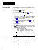
3. Determine the input or device causing the fault from the
section/sub-section heading in Table 7.D where the fault code was
tabulated and from other figures or tables referred to.
4. Interpret the messages. Was this output supposed to be on? Was that
device supposed to be off?
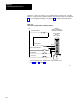
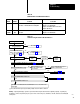
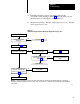
Figure 7.3
Troubleshooting
Flowchart for Diagnostic diagnostic message codes
Press will not run.
Is a diagnostic message
displayed?
See Table 7.C
Does the problem relate to an
input switch or connection?
Go to figure 7.2
Yes
No
No
12291
Does the problem relate to a
solenoid or its triac?
No
Take action according to Table
7.C
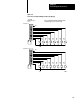
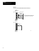
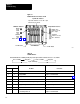
Is a blown fuse indicator on for
any 1771OD module? (See
Figure 7.1)
Replace the fuse.
No
Replace the 1771OD module or
the solenoid. Check solenoid
wiring.
Yes
Yes
Does the status indicator for the
input to the 1771IA module
respond correctly? (See Figure
7.1)
Yes
Replace the 1771IA module.
No
Replace the input switch or
check its wiring.
Warning: To guard against injury to personnel, open and lock the main power disconnect before adjusting, replacing, or repairing any
mechanical or electrical component in your press system. This consists of the press, clutchbrake, controller, and all associated wiring and
control panels.