
Manual

Field Wiring Arm Connections
Chapter 6
626
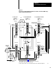
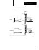
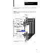
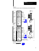
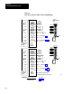
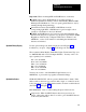
Figure 6.12
Connections for Operator Stations 3 and 4, and Dummy Plugs
2L2
Chassis A
2L2
Chassis B
Slot 0
Ch A-0
Ch B-1
Ch A-2
Left Run
Left Active
Left 2L1
Ch B-0
Ch A-1
Ch B-2
Right Run
Right Active
Right 2L1
Stop-On-Top
E-stop
Dummy Plug
for Station
Bypass
See figure 6.10
See figure 6.1 or 6.5
2L1
Ch A-3
Ch B-4
Ch A-5
Left Run
Left Active
Left 2L1
Ch B-3
Ch A-4
Ch B-5
Right Run
Right Active
Right 2L1
Stop-On-Top
E-stop
Dummy Plug
for Station
Bypass
Plug-in
Operator
Station 4
See figure 6.10
See figure 6.1 or 6.5
2L1
Ch A-0
Ch A-1
Ch A-2
Ch A-3
Ch A-4
Ch A-5
Ch B-0
Ch B-1
Ch B-2
Ch B-3
Ch B-4
Ch B-5
Plug either the operator station
or dummy plug into the control panel.
17880
A
0
1
2
3
4
5
6
7
A
0
1
2
3
4
5
6
7
IMPORTANT:
For These Connections
See Figures
E - STOP
STOP-ON-TOP
6.1 or 6.5
6.10
Plug-in
Operator
Station 3
B
B
1771-IA
Module Group 1