
Manual
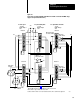

Field Wiring Arm Connections
Chapter 6
622
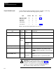
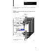
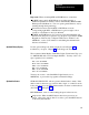
Connect hardwire inputs in parallel to chassis A and B so each voting
processor can monitor the following inputs in parallel:
Input Terminal MG Slot Figure
Mode
Select Switch
Main Motor Forward
Barrier Guard
Stopontop
Arm Continuous
Press Interlock
03
4
5
6
7
6
0
0
0
0
0
2
0
0
0
0
0
0
6.10
6.1, 6.5
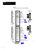
When connected, these inputs function as follows:
This
Input
With
PM in
this Mode
W
ith this
Status
The PM module:
Mode Select (terminals 03)
Determines
the mode
ON
detects the selected mode
Main Motor Forward (terminal 4) Inch or
Microinch
ON or OFF
uses these signals to determine proper CAM action
Single stroke
and
Continuous
ON
detects one of the permissives to start or maintain a stroke
if turned OFF
after motion
has started
immediately turns OFF solenoid outputs
Barrier Guard (terminal 5)
Continuous OFF
prevents press from starting, or stops it immediately
Arm Continuous (terminal 7)
Continuous,
only
momentary
(less than 3 sec)
Each ON/OFF transition starts a 5sec period in which you must
press all
active RUN buttons to start continuous stroking.
Pressing Arm Continuous again within 5 seconds starts another
5sec period.
Press Interlock (terminal 6)
chassis A & B MG 2, Slot 0
any ON
if turned OFF
detects one of the permissives to start or maintain a stroke after
transition
immediately stops the press, or prevents it from starting
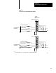
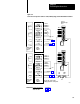
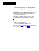
WARNING: To guard against injury to personnel, wire you
barrier guard switch exactly as shown in Figure 6.10.
Conform to all requirements for safeguarding the point of
operation of your press as detailed in OSHA Regulations,
Title 29-Labor, Chapter XVII, Section 1910.217.
Required Hardwire Inputs