
Manual
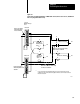

Field Wiring Arm Connections
Chapter 6
612
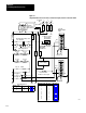
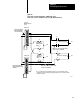
Figure 6.1
Ungrounded
AC Power Connections, Crowbar T
est Inputs, and Press Interlock Switch
2L2
Chassis A
2L2
Chassis B
1771-IA
Slot 0
F
u
s
e
F
u
s
e
E-stop
Station 2
E-stop
Station 1
E-stop
E-stop
Station 3
E-stop
Station 4
1LT 2LT
Ground Fault Lamps and
Text Switches
H
1
H
3
H
4
H
2
X
12
X
120V
AC
Isolation/
Step Down
Transformer
Seal A
Seal B
Start
Crowbar A
Crowbar B
3L1 3L2
F
u
s
e
1
L
F
u
s
e
L
2
F
u
s
e
L
3
Incoming
AC
Disconnect
1L1
1L2 1L3
To Motor Starters
Back Panel
Ground Bus
Equipment
Grounding
Conductors
To Earth
Ground
F
u
s
e
F
u
s
e
2L1
2L2
Processor
Power Supply
2
L1
2L2
3L1
3L1
Press Interlock
Crowbar A Test Input
Crowbar B Test Input
12268
A
0
1
2
3
4
5
6
7
B
A
0
1
2
3
4
5
6
7
Module group
3
4
Sl
o
t
0
0
Figure
6.3
6.4
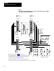
120V AC Power for:
Modul
e
group
0
0
1
1
2
2
3
4
5
5
Slot
0
1
0
1
0
1
1
1
0
1
Figure
6.10
6.11
6.12
6.9
6.2
6.3
6.14
6.4
6.4
6.13
120V AC Power for:
Module Group 2
B
Customer Contacts