
Manual

Field Wiring Arm Connections
Chapter 6
68
Optional Motion Detectors and Air Pressure Switches
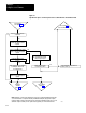
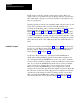
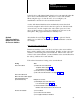
For either one of these optional features, you may use a single switch or
redundant switches (Figure 6.2 or 6.6):
For
this wiring And this feature
Follow these instructions
Singleswitch Motion detector
Connect the jumper between terminal 1 (chassis A)
and terminal 1 (chassis B)
Air pressure
Connect the jumper between terminal 2 (chassis A)
and terminal 2 (chassis B)
either of above
Omit dottedline wiring for redundantswitch circuits
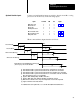
Redundantswitch
Motion detector
Remove the jumper between terminal 1 (chassis A)
and terminal 1 (chassis B)
Air pressure
Remove the jumper between terminal 1 (chassis A)
and terminal 1 (chassis B)
either of above
Add dottedline wiring for redundantswitch circuits
(for motion detector and/or air pressure)
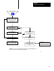
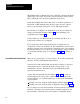
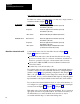
Connect main valve solenoids A and B as shown in Figure 6.3 or
Figure 6.7 with these connections:
feedback from main valve solenoid triacs that allows both voting
processors to monitor the on or off state of each triac, and check for
shorted or open triacs, and open or shorted main valve solenoids.
load resistors, LRA and LRB, for triac feedback from main valve
solenoids A and B
crowbar relay coils and seal relay coils
If your main valves use valve stem switches for external fault detection,
you must configure for valve stem fault detection by setting backplane
switches (chapter 3) and programming configuration bits (chapter 4).
Then, your optional auxiliary and/or dump valves must also use valve
stem switches. If not, you must simulate their inputs by jumpering their
input terminals to the input terminals for the main valve stem switches.
If your valves have internal fault detection (no valve stem switches), do
not configure for valve stem fault detection, and delete valve stem input
connections from Figure 6.4 or Figure 6.8 and Figure 6.2.
Each main valve solenoid should draw at least 60mA. If not, connect an
appropriate load resistor in parallel with it. For neatness and safety, we
recommend that you connect feedback and load resistors only at
convenient terminal strips, not at the field wiring arms.
Main Valve Solenoids A and B