
Manual

Field Wiring Arm Connections
Chapter 6
65
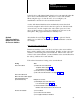
Connect optional hardwire inputs as needed to chassis A and B so voting
processors can monitor any of the following inputs:
Input Terminal MG Slot Figure
Main
V
alve Stem
Motion Detector
Air Pressure
Auxiliary V
alve Stem
Microinch V
alve Stem
Microinch Air Pressure
Dump V
alve Stem
0
1
2
7
1
2
4
2
2
2
2
5
5
4
0
0
0
0
0
0
1
6.2 or 6.6
6.4 or 6.8
6.4, 6.8
6.4, 6.8
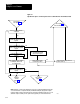
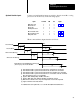
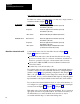
When connected these inputs function as follows:
Triac Command
ON
OFF
Triac Feedback
ON
OFF
ON OFF
OFF
ON
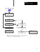
For additional valve stem requirements, see section title Internal/External Fault Detection
0100ms
0100ms
Air
Pressure Feedback
V
alve Stem Feedback
Applies
to firmware revision A/D and later
Applies
to Main, MicroInch, Auxiliary
, and Dump (if configured) solenoids
Applies
to Main, Auxiliary, Dump, and Microinch valves
OFF
0 100ms
[1]
[2]
[5]
[6]
0510ms
[3]
[4]
0200ms
[4]
0500ms
[4]
04 seconds
[4]
[7] [8]
Motion Detector must turn ON before upstroke
(before Topstopcheck cams turn OFF
[1]
[2]
[3]
[4]
[5]
[6]
[7]
[8]
Time
window for faultless operation measured from Triac Command of
ftoon transition
Time
window for faultless operation measured from T
riac Feedback of
ftoon transition
Time
window for faultless operation measured from Valve Stem feedback of
ftoon transition
Time
window for faultless operation measured from ontoof
f transition of the T
riac Command.
Ontoof
f transitions need not occur sequentially
.
Motion Detector transition of
ftoon is position dependent, ontoof
f is time dependent
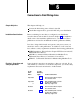
Optional Hardwire Inputs