
Manual

Field Wiring Arm Connections
Chapter 6
62
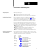
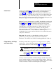
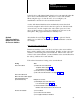
Use
This
Mandatory
Figure
For These Connections
6.9
Cam Limit Switch Assemblies
6.10
Main Motor Forward
Barrier Guard
Stopontop
Arm Continuous
Mode Select Switch
6.11
Operator Stations 1 & 2
Dummy Plugs
Inch Pushbutton Switches
WARNING: To guard against injury to personnel and
damage to your press, connect your clutch/brake controller
exactly as shown in these figures.
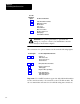
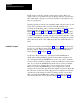
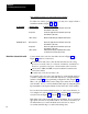
The connections for optional features are shown in the following figures:
Use
this Figure
For These Optional Connections
6.2 or 6.6
6.4 or 6.8
6.12
6.13
6.14
Switches on
Main V
alve Stems
Air Pressure Sensors
Motion Detector
Dump and/or Microinch V
alves
Operator Stations 3 & 4
Dummy plugs
Diagnostic Message Display
Brake Fault Indicator
Run Window Indicator
Microinch Indicator
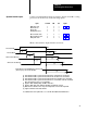
Important: Use 14 AWG stranded copper wire with 3/64-inch insulation
for all solenoid and relay coil connections to the 1771-OD modules. We
also recommend the same wire size for all field wiring arm connections.