
Manual

Voting Processor Firmware
Chapter 5
512
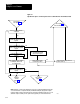
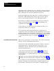
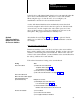
Figure 5.7
Operational
Sequence for First Upstroke and Second Downstroke in Continuous Mode
First Upstroke.
From figure 5.6
Both voting processors continue
actuating the clutch for the first
upstroke
Has an operator released a RUN
button, or has the barrier guard
opened?
Is the shaft in the neartop
position?
Select inch mode and position the
shaft near the top.
NOTE: Halfstroke or Strokeandahalf requires all operators to hold all RUN buttons until the first
or second downstroke is completed. Releasing a RUN button during the (first) upstroke requires
restarting continuous mode at the arming sequence. Releasing a RUN button in the first or second
downstroke requires restarting as if an operator had stopped the press in the first downstroke.
12266
Yes
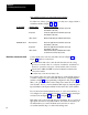
Did the shaft stop in the
nearbottom position?
Has 1/2 or 1 1/2 stroke been
configured?
Yes
No
Both voting processors continue
actuating the clutch for the
second downstroke
Has an operator released a RUN
button, or has a barrier guard
opened?
No
Yes
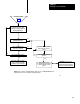
Go to Figure 5.5
Select Continuous Mode
No
Yes
No
Go to
Continuous
Stroking
Figure 5.8
Go to
Stop Condition
Figure 5.6
Yes
No
Both voting processors
de-energized their solenoid
triacs to stop the press.