
Manual

PC Ladder Programming
Chapter 4
412
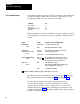
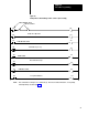
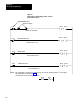
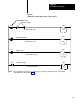
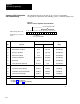
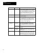
We summarize the bits in module group 7 used for determining
configuration requirements and enabling operator commands (Figure 4.9).
Figure 4.9
Functions
of PLC Configuration and Command Bits
17161514131211100706050403020100
PLC Command Bits
Output image table word,
Module Group 7, Chassis
A & B
PLC Configuration Bits
Bit Bit
Status
T
ype of
No: Function: Set Reset Rung:
01
Stations 3 and 4
Used
Not Used
Unconditioned
02
Motion Detector Feedback
Used
Not Used
Unconditioned
03 V
alve Stem Feedback
Used
Not Used
Unconditioned
04
Air Pressure Feedback
Used
Not Used
Unconditioned
05
AC Power Configuration
Ungrounded Grounded Unconditioned
06 OnTheHop Used
Not Used
Unconditioned
07
Strokeandahalf or Halfstroke
Not Used
Used Unconditioned
10
Press Enable (PLC Command)
Enabled Disabled Conditioned
11 StopOnT
op (PLC Command)
Enabled Disabled Conditioned
12
Latched Messages (PLC Command)
Enabled Disabled Conditioned
13
Lamp T
est (PLC Command)
Enabled Disabled Conditioned
14
Dump V
alve T
riacs Used
Not used
Unconditioned
NOTES: Do not use bits 00 and 15 17 for any purpose.
See Figure 4.2
for bit addresses
See Figure 4.3
through 4.8 for programming
12254
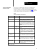
Summary of PLC Configuration
and Command Rungs