
Manual

PC Ladder Programming
Chapter 4
49
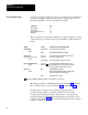
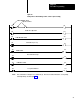
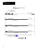
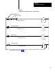
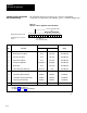
Figure 4.6
Example
PLC Command Rungs for Bits 10 thru 13 (PLC2 Family)
132
13
057
10
PRESS ENABLE Switch
Optional conditions
13
067
10
Enable Press Operation
132
15
057
11
132
15
067
11
132
14
057
12
132
14
067
12
132
16
057
13
132
16
NOTE:
067
13
STOP-ON-TOP Switch
RESET Switch
Reset latched messages
LAMP TEST Switch
Test optional indicators
Command Stop-on-top
132
PLC command bits 10 through 13 use conditioned logic. Do not latch or unlatch instructions. Corresponding
switch input wiring is shown in Figure 6.15.