
Manual

PC Ladder Programming
Chapter 4
48
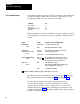
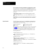
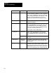
Your ladder diagram program can send four commands to the clutch/brake
controller by setting command bits 10-13 in the output image word for
module group (MG) 7, Slot 1 for I/O chassis A and B:
Command Bit
Press
enable
Stopontop
Reset latched messages
Lamp test
10
11
12
13
These commands can be issued manually by an operator pushing a switch,
or automatically by a switch closure in your machinery. They function as
follows:
Output Status Condition
Controlled by PM Module
Press Enable
Bit 10
must be ON
OFF
T
o enable motion in any mode
Immediately turns OFF triac outputs
Stopontop
(Continuous mode, only)
Bit 1
1
offtoon
transition
must be OFF
T
urns OFF solenoid outputs the next time the
runon cam switches open
T
o start or maintain continuous stroking
Reset Latched Message
Bit 12
offtoon
transition
1
Clears any latched or tripped message code
shown in MG 5, Slot 1, as long as the condition
that caused the message no longer exists.
Lamp T
est
Bit 13
ON
OFF
T
urns ON all these outputs
Brake Fault , Run Window
, Microinch Message,
and other diagnostic message lamps
T
urns OFF these outputs
1
Holding this bit ON may inhibit the capture of subsequent L or t messages.
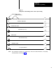
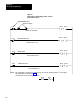
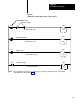
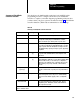
Bit addresses for these command bits are shown in Figure 4.2. Example
PLC command rungs are shown in Figure 4.6 through Figure 4.8.
To enable these commands, write ladder program rungs that are
conditioned with examine-on/examine-off instructions to monitor
corresponding switch inputs wired to I/O chassis C. You can use any
available discrete module terminals (excluding those in chassis A or B)
for these inputs (Figure 6.15). For additional information refer to chapter
6, Inputs to Chassis C .
PLC Command Rungs