
Manual

PC Ladder Programming
Chapter 4
47
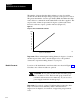
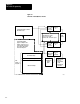
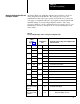
As listed in Table 4.A, backplane switch positions 2 thru 8 correspond
with configuration bits 01 thru 07. The voting processors in your
clutch/brake modules allow press operation only if the set (on) and reset
(off) states of configuration bits in your program correctly match the ON
and OFF settings of corresponding backplane switches. The voting
processors check for correct configuration when you apply power to your
clutch/brake controller or change its mode of operation using the mode
select switch.
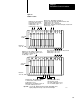
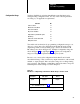
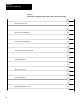
Table 4.A
Corresponding
Backplane Switch Settings and Configuration Bits
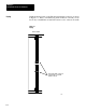
Backplane
Switch
Settings
(figure 3.3)
Configuration
Bits
Backplane switch settings and configuration bits
must be identical
Pos. Setting Bit: Status: Function:
2 ON 01 Set
Use Stations 3 and 4
OFF reset
Stations 3 and 4 not used
3 ON 02 set
Use Motion Detector Feedback
OFF reset
Motion Detector Feedback not used
4 ON 03 set
Use V
alve Stem Feedback
OFF reset V
alve Stem Feedback not used
5 ON 04 set
Use Air Pressure Feedback
OFF reset
Air Pressure Feedback not used
6 ON 05 set
Ungrounded AC Power
OFF reset
Grounded AC Power
7 ON 06 set
Use OnTheHop
OFF reset
OnTheHop not used
8 ON 07 set
Use Halfstroke
OFF reset
Use StrokeAndAHalf
Module Group 4
Slot 1, Chassis A&B
1771IA
Set
Use Dump V
alve Outputs
Module Group 4
Slot 1, Chassis A&B
is EMPTY
14
reset
Dump V
alve Outputs not used
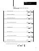
Matching Configuration Bits and
Backplane Switches