
Manual

PC Ladder Programming
Chapter 4
45
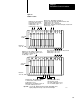
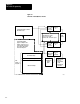
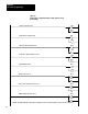
Figure 4.4
Example PLC Configuration Rungs for Bits 01 thru 07 and 14
(PLC3 and PLC5/250)
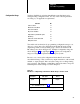
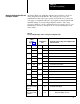
U
O0057
01
Stations 3 and 4 not used
U
O0067
01
(
L
O0057
02
L
Valve stem switch feedback used
U
04
Air pressure switch feedback not used
L
05
Ungrounded AC power
U
On-the-hop not used
U
07
L
14
Optional dump valve triacs used
)
)
)
)
)
)
)
O0067
02
(
O0067
03
(
U
O0067
04
(
O0067
05
(
U
O0067
06
(
U
O0067
07
(
O0067
14
(
O0057
O0057
O0057
O0057
O0057
O0057
NOTE: Unconditionally latch or unlatch bits 0 through 7 and 14 for chassis A and B as shown to use these functions.
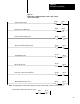
L
L
L
L
06
Use this address format for PLC-5/250 processors
U
01
)
O:067
01
(
O:057
U
Motion detector feedback used
03
Half-stroke or Stroke-and-a-half used