
Manual

PC Ladder Programming
Chapter 4
43
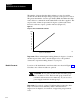
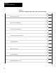
You have flexibility in selecting clutch/brake controller functions by
setting/resetting configuration bits. Use any of the following functions
according to your application requirements:
Functions Bit
Stations
3 and 4
01
Motion detector feedback
02
V
alve stem feedback
03
Air pressure feedback
04
Ungrounded or grounded AC power
05
Onthehop 06
Halfstroke or Strokeandahalf
07
Dump valve circuit
14
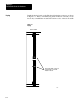
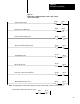
You enable various functions by programming configuration rungs to set
(turn on) or reset (turn off) configuration bits 01 thru 07 and 14 in the
output image table word for module group 7, chassis A and chassis B.
Bit addresses are shown in Figure 4.2. Example configuration rungs are
shown in Figure 4.3 through Figure 4.5. Program your configuration
rungs according to the requirements of your press system.
Be sure to set or reset each configuration bit 01 thru 07 and 14 with
unconditioned rungs. They contain only output instructions, such as latch,
unlatch, or output energize. Bits set by these rungs do not change during
press operation. The latching or unlatching of these bits must correspond
with backplane switch settings covered in chapter 3.
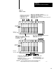
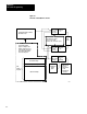
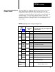
Figure 4.2
Bit
addresses of Output Image T
able W
ord for Module Group 7 of Chassis A & B
PLC-2/20 PLC-3
PLC-2/30 PLC-5/250
PLC-5
0y7/xx Oyy7/xx O:y7/xx
where yy = rack address per Figure 3.4
xx = bit number 00 - 17
Important: Do not use bits 00 and 15-17 for any purpose.
Configuration Rungs