
Manual

Clutch/Brake Controller Hardware
Chapter 3
314
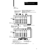
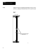
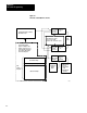
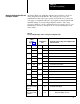
Install the keying bands on the I/O chassis backplane connector as shown
in Figure 3.7. After you install keying bands in chassis A and B, you can
insert only a clutch/brake module in the left-most slot of chassis A and B.
Figure 3.7
Keying
2
4
6
8
10
12
14
16
18
20
22
24
26
28
30
32
34
36
38
40
42
44
46
48
50
52
54
56
2
4
6
8
10
12
14
16
18
20
22
24
26
28
30
32
34
36
38
40
42
44
46
48
50
52
54
56
Insert keying bands so that you
can install only a 1771-PM
module in this slot.
12252
Chassis A and B
Keying