
Manual

Clutch/Brake Controller Hardware
Chapter 3
36
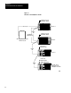
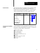
Although this manual describes a single clutch/brake controller, you may
connect your PLC to multiple controllers, each controlling a separate
press. Each clutch/brake controller uses two remote I/O racks for chassis
A and B. For example, since a PLC-3 controller can support as many as
32 I/O racks, you may connect it to as many as 15 clutch/brake controllers
with two additional I/O racks for modules in chassis C.
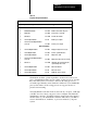
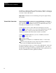
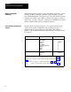
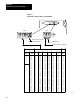
You can operate your press using up to four operator stations and an
optional control panel. Installations vary according to the type of
mechanical press and its application requirements. The number of
stations, control switches contained in each, and the control panel could
be as follows:
Assembly Control
Switches
Notes
Control Panel and/or Station 1
Mode select
Arm continuous
Stopontop
L/R Inch
Press enable
Reset latched messages
Lamp test
L/R Run
EStop
1
1
1 and/or 3
2
3
3
3
2
2
Stations 2 thru 4
L/R Run
Stop On T
op
EStop
2
2 and/or 3
2
1
Connect
these
switches
to
input
modules
in
chassis
A
and
B
(Figure
6.10).
2
Connect
these
switches
to
input
modules
in
chassis
A
and
B
(Figures
6.11
thru
6.12).
3
These
switches
are
inputs
for
command
rungs
(Figures
4.6
thru
4.8).
Connect
these
switches
to
input
modules
in
remote
I/O
chassis
C
(Figure
6.15).
Multiple Clutch/Brake
Controllers
Panel Switches and Operator
Stations