
Manual

Appendix
B
B1
I/O FROM /TO LISTS
In the following tables of from/to lists, we use the notation CGST to
designate field wiring arm terminals, where
C = chassis A or B S = slot number
G = module group T = terminal number
For example, a connection to chassis A, module group 3, slot 1, terminal
12 would be designated A3112.
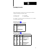
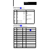
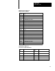
I/O
From/T
O List for Figure 6.1
3L1 Power
, Crowbar T
est and press Interlock Inputs
From To
A203
A204
A206
A20B
B203
B204
B206
B20B
3L1
Crowbar as (NO) contact
B206
2L2
3L1
Crowbar B (N)) contact
Press Interlock Switch
2L2
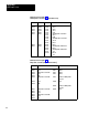
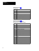
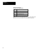
I/O From/To List for Figure 6.2
Main Solenoids, Crowbar and Seal-In Relays (Ungrounded AC Power)
From To From To
A210
A210
A211
A212
A212
A213
A21B
A302
B210
B211
A304
B212
B213
2L2
A302
A302
A304
A304
A3010
A3012
LRA
Main V
alve Soelnoid A
LRB
Main V
alve SOlenoid B
Crowbar Relay A
Seal Relay A
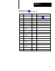
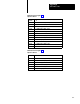
B211
B213
B21B
B301
B303
2L2
B301
B303
B3010
B3012
Main V
alve Solenoid A
Main V
alve Solenoid B
Crowbar Relay B
Seal Relay B