
Manual

Troubleshooting
Chapter 7
738
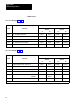
Diagnostic
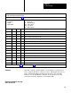
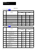
message codes are displayed by indicators connected to module group 5, slot 1 (figure 6.18), or by displaying the corresponding
data table word using the industrial terminal.
Use this table in conjunction with figure 7.1 and figure references shown in parentheses.
T
ype of Message
N = Nonlatched
L = Latched
T = T
rip Condition
Code
P = at Powerup
Alt = Alternate chassis
Ethr = Either chassis
Top = T
op chassis
Bot = Bottom chassis
Binary Hex Type Code
Diagnostic Message (figure References)
Other Cam Limit Switch Faults
(Figures 5.1, 6.1
1)
1010 1000
A8 N P
Cam switches cannot determine shaft position. Inch to top.
1010 1001
A9 N P
All cam switches are open.
1010 1010
AA L
Cam switches cannot determine shaft position. Inch to top.
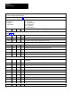
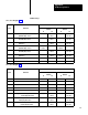
General Faults
1010 101
1 AB N
Not used.
1010 1
100 AC L
Crowbar test input is ON. Check wiring of crowbar testt circuit
1010 1
101 AD N A
waiting turn of
f of crowbar relay test.
1010 1
110 AE N A
waiting turn of
f of crowbar relay test.
1010 1
111 AF N A
waiting solenoid power
.
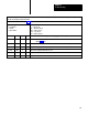
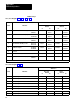
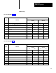
Configuration Error
101
1 0000
B0 N Alt
Configuration error in alternate module. Configure it correctly or match inputs to your
configuration.
101
1 0001
B1 N T
urn of
f backplane switch 1.
101
1 0010
B2 N
Stations 3 and 4 configuration bitr and backplane switch mismatched
101
1 001
1 B3 N
Motion detector configuration bit and backplan switch mismatched.
101
1 0100
B4 N V
alve stem switch configuration bit and backplance switch mismatched.
101
1 0101
B5 N
Air pressure switch configuration bit and backplane switch mismatched.
101
1 01
10 B6 N
Ungrounded/grounded AC power configuration bit and backplane switch mismatched.
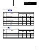
101
1 01
11 B7 N
Onthehop configuration bit and backplane switch mismatched.
101
1 1000
B8 N
Strokeandahalf configuration bit and backplane switch mismatched.
101
1 1001
B9 N
Dump valve configuration bit disagrees with corresponding I/O modules in chassis.
101
1 1010
BA N
An I/O input module is missing.