
Manual

Troubleshooting
Chapter 7
737
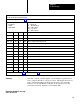
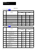
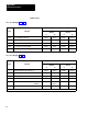
diagnostic message codes are displayed by indicators connected to module group 5, slot 1 (figure 6.18), or by displaying the corresponding
data table word using the industrial terminal.
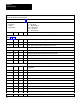
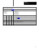
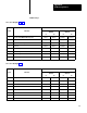
Use this table in conjunction with figure 7.1 and figure references shown in parentheses.
T
ype of Message
N = Nonlatched
L = Latched
T = T
rip Condition
Code
P = at Powerup
Alt = Alternate chassis
Ethr = Either chassis
Top = T
op chassis
Bot = Bottom chassis
Binary
Diagnostic Message (figure References)
CodeTypeHex
1 1
101 1000
1D8 T Ethr T
riac 8 remains on after triacs turn of
f.
1 1
101 1001
1D9 T Ethr T
riac 9 remains on after triacs turn of
f.
1 1
101 1
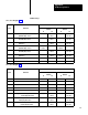
110 1DE T
Microinch valve stem input is on when triacs are of
f.
1 1
101 1
111 1DF T Alt
Microinch valve stem input is on when triacs are of
f.
1 11
10 0100
1E4 T
Microinch valve stem input is of
f when triacs are on.
1 11
10 0101
1E5 T Alt
Microinch valve stem input is of
f when triacs are on.
1 11
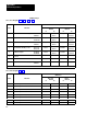
10 1010
1EA T
Microinch valve stem input remains on after triacs turn of
f.
1 11
10 1000
1E8 T Alt
Microinch valve stem input remains on after triacs turn of
f.
1 1111 1111 1FF N
Lamp test in progress
2
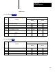
Refer
to ACTIVE indicator (table 7.A) or F
AUL
T indicators (table 7.B).
Now that you have read this chapter, you should have a general idea of
how to safely troubleshoot your press system. This chapter showed you
how to interpret the diagnostic diagnostic message codes and status
indicators of your clutch/brake controller. It also referred you to the
associated connection diagrams for locating the fault.
Summary
Diagnostic diagnostic message
codes in Table 7.C