
Manual

Clutch/Brake Controller Hardware
Chapter 3
33
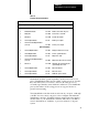
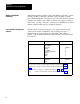
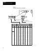
Table 3.A
Required and Optional Hardware
Quantity Item
Cat. No.
Function
Important: (Y
ou must use 8point modules with 2slot addressing)
Required Hardware
2
Clutch/Brake Module
1771PM
Monitors and controls the press
2
Wiring Arm
1771WB
Connections to 1771PM
2
I/O Chassis
1771A2B
Contains the modules
10
120V AC Input Modules
1771IA
Monitors press inputs
2
120V AC Isolated Output Modules
(Series C)
1771OD
Controls press outputs
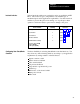
Optional Hardware
2
120V AC Output Modules
1771OA
Display of diagnostic messages
1
120AC Output Module
1771OA
Controls optional indicators
2
120V AC Input Modules
1771IA
Dump valve circuit
2
120V AC Isolated Output Modules
(Series C)
1771OD
Dump valve and/or microinch circuit
2
I/O chassis
1771A4B
Substitute chassis when using the
optional dump valve circuit.
1
120V AC Output Module
1771OA
Microinch indicator
2
120V AC Input Modules
1771IA
Microinch circuit
2
120V AC Input Modules
1771IA
Additional operator stations
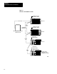
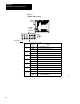
Clutch/brake modules operate in parallel to monitor and control your
press. Clutch/brake modules are also called “voting processors” because
they must always have a consensus. Unless both voting processors
constantly agree that they sense identical conditions in your clutch/brake
press system, either or both voting processors stop press motion or
prevent it from starting.
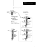
Your clutch/brake controller monitors and controls your press. Although
your PLC does not control your press, it does configure and enable the
clutch/brake controller. Your PLC ladder program can monitor inputs to,
and the status of, your clutch/brake controller. This allows your PLC to
control other indicators, machines, or processes related to your press
system.