
Manual

Troubleshooting
Chapter 7
734
diagnostic
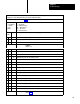
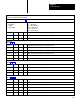
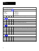
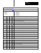
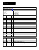
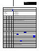
message codes are displayed by indicators connected to module group 5, slot 1 (figure 6.18), or by displaying the corresponding
data table word using the industrial terminal.
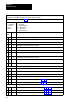
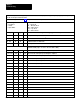
Use this table in conjunction with figure 7.1 and figure references shown in parentheses.
T
ype of Message
N = Nonlatched
L = Latched
T = T
rip Condition
Code
P = at Powerup
Alt = Alternate chassis
Ethr = Either chassis
Top = T
op chassis
Bot = Bottom chassis
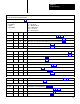
Binary
Diagnostic Message (figure References)
CodeTypeHex
1
101 0001
D1 T Top T
riac 7 off when commanded on.
1
1101
0010
D2 T Ethr T
riac 0 of
f when commanded on.
1
1101
001
1 D3 T Ethr T
riac 1 of
f when commanded on.
1
1101
0100
D4 T Ethr T
riac 2 of
f when commanded on.
1
1101
0101
D5 T Ethr T
riac 3 of
f when commanded on.
1
1101 0110 D6 T Ethr T
riac 6 of
f when commanded on.
1
1101 0111 D7 T Ethr T
riac 7 of
f when commanded on.
1
1101
1000
D8 T Top T
riac 0 remains on after turned of
f.
1
1
101 1001
D9 T Top T
riac 1 remains on after turned of
f.
1
1
101 1010
DA T Top T
riac 2 remains on after turned of
f.
1
1
101 101
1 DB T Top T
riac 3 remains on after turned of
f.
1
1
101 1
100 DC T Top T
riac 6 remains on after turned of
f.
1
1
101 1
101 DD T Top T
riac 7 remains on after turned of
f.
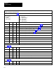
1
Fault in V
alve Stem Feedback
1
101 1
110 DE T
Main valve stem signal on when triacs are of
f.
1
1
101 1
111 DF T Alt
Main valve stem signal on when triacs are of
f.
1
11
10 0000
E0 T
Aux. valve stem signal on when triacs are of
f.
1
11
10 0001
E1 T Alt
Aux. valve stem signal on when triacs are of
f.
1
11
10 0010
E2 T
Dump valve stem signal on when traics are of
f.
1
11
10 001
1 E3 T Alt
Dump valve stem signal on when traics are of
f.
1
11
10 0100
E4 T
Main valve stem signal of
f when triacs are on.
1
11
10 0101
E5 T Alt
Main valve stem signal of
f when triacs are on.
1