
Manual

Troubleshooting
Chapter 7
728
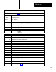
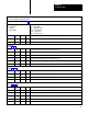
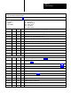
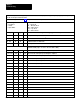
Diagnostic message codes are displayed by indicators connected to module group 5, slot 1 (figure 6.18), or by
displaying the corresponding data table word using the industrial terminal.
Use this table in conjunction with figure 7.1 and figure references shown in parentheses.
T
ype of Message
N = Nonlatched
L = Latched
T = Trip
Condition
Code
P = at Powerup
Alt = Alternate chassis
Ethr = Either chassis
Top = T
op chassis
Bot = Bottom chassis
Hex
Code
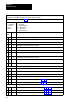
Diagnostic Message (figure References)
Type
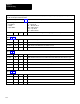
50
Swingarm power absent
51 N
INCH button not released. Check (NO) contacts.
52 Alt N
INCH button not released. Check (NO) contacts.
53 N
INCH button not released. Check (NC) contacts.
54 Alt N
INCH button not released. Check (NC) contacts.
55 P N
INCH button not released. Check (NC) contacts.
56 P,
Alt
N
INCH button not released. Check (NC) contacts.
57 P N
INCH button not released. Check (NC) contacts.
58 P,
Alt
N
INCH button is not released. Check (NO) contacts).
59
Not used.
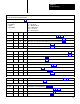
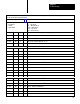
V
alve Stem Inputs Not Configured
5A T
Main valve stem input is present but not configured. (6.17)
5B Alt T
Main valve stem input is present but not configured. (6.17)
5C T
Auxiliary valve stem input is present but not configured. (6.17)
5D Alt T
Auxiliary valve stem input is present but not configured. (6.17)
5E T
Dump valve stem input is present but no configured. (6.4, 6.9)
5F Alt T
Dump valve stem input is present but no cinfigured. (6.4, 6.9)
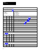
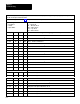
Downstroke Fault
60 L
RUN button in station 1 released too late in the downstroke.(5.3,5.6,6.13)
61 L
RUN button in station 1 released too late in the downstroke.(5.3,5.6,6.13)
62 L
RUN button in station 1 released too late in the downstroke.(5.3,5.6,6.13)