
Manual

Troubleshooting
Chapter 7
726
Diagnostic message codes are displayed by indicators connected to module group 5, slot 1 (figure 6.18), or by
displaying the corresponding data table word using the industrial terminal.
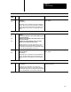
Use this table in conjunction with figure 7.1 and figure references shown in parentheses.
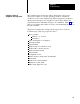
T
ype of Message
N = Nonlatched
L = Latched
T = Trip
Condition
Code
P = at Powerup
Alt = Alternate chassis
Ethr = Either chassis
Top = T
op chassis
Bot = Bottom chassis
Hex
Code
Diagnostic Message (figure References)
Type
28 T
Active input changed from closed to open. Check wiring.
29 Alt T
Active input changed from closed to open. Check wiring.
2A T
(NC) RUN button bypass is open. Check wiring
2B Alt T
(NC) RUN button bypass is open. Check wiring
2C T
(NO) RUN button bypass is open. Check wiring
2D Alt T
(NO) RUN button bypass is open. Check wiring
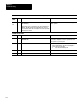
2E
Not Used.
2F
Not Used
Station 3
(Figure 6.15)
30 N
Check configuration of RUN button signals. Make station active or bypassed
31 N
RUN button not released. Check (NO) contacts.
32 Alt N
RUN button not released. Check (NO) contacts.
33 N
RUN button not released. Check (NC) contacts.
34 Alt N
RUN button not released. Check (NC) contacts.
35 P N
Make left and right active connections identical.
36 P N
(NC) RUN button is open. Check button or wiring.
37 P N
(NO) RUN button is shorted. Check button or wiring.
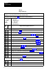
38 T
Active input changed from closed to open. Check wiring.
39 Alt T
Active input changed from closed to open. Check wiring.
3A T
(NC) RUN button bypass is open. Check wiring
3B Alt T
(NC) RUN button bypass is open. Check wiring
3C T
(NO) RUN button bypass is open. Check wiring