
Manual

Troubleshooting
Chapter 7
724
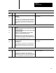
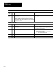
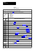
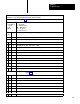
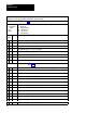
Table 7.D
Diagnostic
Messages
Diagnostic message codes are displayed by indicators connected to module group 5, slot 1 (figure 6.18), or by
displaying the corresponding data table word using the industrial terminal.
Use this table in conjunction with figure 7.1 and figure references shown in parentheses.
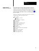
T
ype of Message
N = Nonlatched
L = Latched
T = Trip
Condition
Code
P = at Powerup
Alt = Alternate chassis
Ethr = Either chassis
Top = T
op chassis
Bot = Bottom chassis
Hex
Code
Type
Diagnostic Message (figure References)
Press Operation Inhibited
01 N
Improper mode selection (6.12)
02 N
All stations bypassed. (6.13 thru 6.16)
03 N
Shaft not near top. Can not enter single or continuous mode. (5.1, 6.1
1)
04 N A
waiting release of all RUN buttons for entering single or continuous mode. (6.13 thru 6.16)
05 N
Main motor forward dropout or absent (6.12)
06 N
Antirepeat cam switch open, preventing entry to single or continuous mode (5.5, 6.1
1)
07 N A
waiting release of all ST
OPONT
OP buttons for entering continuous mode. (5.5, 6.12)
08 N A
waiting release of ARM CONTINUOUS button for entering continuous mode.(5.5, 6.12)
09 N
Barrier guard dropout or absent. (5.5, 6.12)
0A N
PC enable dropout or absent. (4.5, 4.7)
0B N
Stopontop signal from PC preventing entry to continuous mode. (4.5, 4.7)
0C N A
waiting release of INCH buttons for entering inch mode. (5.2, 6.13)
0D N A
waiting solenoid power to reset stop condition. Press EST
OP
, then ST
AR
T buttons. (6.1, 6.6)
0E N
PC run mode dropout or absent.
0F N
Press interlock dropout or absent. (6.2, 6.7)
Station 1
(Figure 6.13)
10 N
Check RUN button signals. Make station active or bypassed.
11 N
RUN button not released. Check (NO) contacts.
12Alt N
RUN button not released. Check (NO) contacts.