Allen Bradley Clutch/Brake Module (Cat. No.
Table of Contents Introduction . . . . . . . . . . . . . . . . . . . . . . . . . . . . . . . . . . . . 1 1 Chapter Objectives . . . . . . . . . . . . . . . . . . . . . . . . . . . . . . . . . . . Objectives Of This Manual . . . . . . . . . . . . . . . . . . . . . . . . . . . . . How To Use This Manual . . . . . . . . . . . . . . . . . . . . . . . . . . . . . . Terminology . . . . . . . . . . . . . . . . . . . . . . . . . . . . . . . . . . . . . . . . Firmware Revision Record . . . . . . . . . . . . . . .
ii Table of Contents Voting Processor Firmware . . . . . . . . . . . . . . . . . . . . . . . . 5 1 Chapter Objectives . . . . . . . . . . . . . . . . . . . . . . . . . . . . . . . . . . . Operation of Voting Processors . . . . . . . . . . . . . . . . . . . . . . . . . . Emergency Shut Down . . . . . . . . . . . . . . . . . . . . . . . . . . . . . . . . Fault Monitoring . . . . . . . . . . . . . . . . . . . . . . . . . . . . . . . . . . . . . Operation of Cam Limit Switches . . . . . . . . . . . . . . .
Table of Contents iii Diagnostic Message Codes (Table 7.C) . . . . . . . . . . . . . . . . . . . . Complete Listing of diagnostic message codes . . . . . . . . . . . . . . . Summary . . . . . . . . . . . . . . . . . . . . . . . . . . . . . . . . . . . . . . . . . Diagnostic diagnostic message codes in Table 7.C . . . . . . . . . . . . 7 13 7 23 7 37 7 37 Bit Monitoring Addresses . . . . . . . . . . . . . . . . . . . . . . . . . A 1 I/O FROM /TO LISTS . . . . . . . . . . . . . . . . . . . . . . . . . .
Chapter 1 Introduction Chapter Objectives This chapter will help you become familiar with the: objectives of this manual procedure for using this manual Objectives Of This Manual We have written this manual to help an electrical engineering technician, or any person with a similar background: design a clutch/brake controller for a mechanical power press using the 1771-PM clutch/brake module.
Chapter 1 Introduction Terminology We define new terms where they first appear in this manual. You should be familiar with the following terms because we use them throughout this manual. a press is a mechanical (part revolution) power press that is actuated by a clutch and stopped by a brake a clutch/brake controller is an Allen-Bradley controller, which includes chassis A and B, two Clutch/Brake Modules (cat. no. 1771-PM), and associated I/O modules.
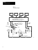
Chapter 2 Press System Description Chapter Objectives This chapter will help you become familiar with: major components of a typical press system safety requirements for a press system System Components A press system, as referred to in this manual, includes: a mechanical power press an Allen-Bradley clutch/brake controller all associated control panels and operator stations all associated output and feedback devices all wires and cables that interconnect system components A functional block diagram o
Chapter 2 Press System Description Figure 2.1 Functional Block Diagram Operator Station No. 1 Operator Station No. 2 Operator Station No. 3 Operator Station No.
Chapter 2 Press System Description Related Safety Documentation This manual concentrates on safety considerations relative to the clutch/brake controller. Study this entire manual and all technical documentation provided by the press manufacturer before you install your press system. In addition to local codes and laws, follow the safety requirements detailed in the following publications: OSHA Regulations, Title 29-Labor, Chapter XVII, Section 1910.217, Mechanical Power Presses ANSI B11.
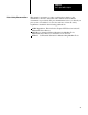
Chapter 3 Clutch/Brake Controller Hardware Chapter Objectives This chapter will help you become familiar with the: hardware components of your Allen-Bradley clutch/brake controller functional relationships between your PLC and clutch/brake controller interconnections between your PLC and clutch/brake controller switch settings that configure your clutch/brake controller and establish its rack addresses General Hardware Considerations For details on how to install the I/O chassis and modules, refer to
Chapter 3 Clutch/Brake Controller Hardware Figure 3.
Chapter 3 Clutch/Brake Controller Hardware Table 3.A Required and Optional Hardware Quantity Item Cat. No.
Chapter 3 Clutch/Brake Controller Hardware In addition to chassis A and B, you must connect your PLC to at least one local or remote I/O chassis, chassis C. You need two, three, or four inputs at a local or remote I/O chassis. Important: You must use 2-slot addressing and 8-point (single-density) I/O modules. Twinaxial Cable Connections Typical twinaxial cable connections of your clutch/brake controller are shown in Figure 3.2.
Chapter 3 Clutch/Brake Controller Hardware Figure 3.2 Typical Twinaxial Cable Connections Terminator (cat. no. 1770 -XT) Processor/Scanner Blue Shield Clear Use Twinaxial Cable (cat. no. 1770 -CD) for all cable connections.
Chapter 3 Clutch/Brake Controller Hardware Multiple Clutch/Brake Controllers Although this manual describes a single clutch/brake controller, you may connect your PLC to multiple controllers, each controlling a separate press. Each clutch/brake controller uses two remote I/O racks for chassis A and B. For example, since a PLC-3 controller can support as many as 32 I/O racks, you may connect it to as many as 15 clutch/brake controllers with two additional I/O racks for modules in chassis C.
Chapter 3 Clutch/Brake Controller Hardware Interlock Switches Various interlock switches are required for safety as specified in ANSI B11.1. The locations, types, and quantities vary with the type of mechanical press and its application requirements. Use these interlock switches to prevent the press from starting or to stop the press when operation could cause injury to personnel or damage to the press. Interlock Switch Quantity Reference Barrier guard 1 or more Figures 6.10 and 6.
Chapter 3 Clutch/Brake Controller Hardware Figure 3.
Chapter 3 Clutch/Brake Controller Hardware Important: There is no backplane switch setting to configure the optional dump valve circuit. You configure the optional dump valve circuit by inserting dump valve modules (cat. no. 1771-OD and 1771-IA) into module group 4, slots 0 and 1, respectively of chassis A and B. You must also set bit 14 unconditionally in your configuration rungs.
Chapter 3 Clutch/Brake Controller Hardware Figure 3.4 Rack Address Switch Setting on 1771 PM Module S W -1 O 1 N O F F 2 3 4 S W -2 5 6 7 O 1 N O F F 8 2 3 4 ON OFF OFF A lw a ys O N (st ar ting M odule G roup 0) A lw ays O F F A lw ays O N (57.
Chapter 3 Clutch/Brake Controller Hardware For example, if you choose rack address 2 for chassis A, you must choose rack address 1 or 3 for chassis B. Set the rack address in each clutch/brake module. Place a label on each clutch/brake module to identify in which chassis, A or B, it belongs. Important: Chassis A and B rack addresses must be unique. No I/O chassis can have the same rack address as either chassis A or B.
Chapter 3 Clutch/Brake Controller Hardware The number of degrees that the shaft continues to rotate, beyond the moment in time when the input changes, depends on the speed of rotation. The greater the number of strokes per minute (SPM), the further the shaft rotates before a command from the clutch/brake controller is applied. The response time of 44ms is represented in degrees of shaft rotation that increases as the rate of press operation increases (Figure 3.5). Figure 3.
Chapter 3 Clutch/Brake Controller Hardware Figure 3.6 Module Locations Required 1771 -IA modules for press inputs chassis A & B module group 0, slots 0 & 1 module group 1, slot 1 module group 2, slots 0 & 1 0 1 2 Optional 1771 -OA modules for display of message codes, brake fault, run window and micro inch.
Chapter 3 Clutch/Brake Controller Hardware Keying Install the keying bands on the I/O chassis backplane connector as shown in Figure 3.7. After you install keying bands in chassis A and B, you can insert only a clutch/brake module in the left-most slot of chassis A and B. Figure 3.
Chapter 4 PLC Ladder Programming Chapter Objectives This chapter will help you become familiar with: programming fundamentals as they relate to your clutch/brake controller the need for press configuration rungs relationships between your press configuration rungs and backplane switch settings relationships between configuration rungs and voting processor firmware the option of monitoring the press through your PLC ladder program the option of using PLC report generation to display messages that you hav
Chapter 4 PC Ladder Programming Figure 4.1 Overview of Clutch/Brake Controller A-B Programmable Controller with Remote I/O 1771 - PM Voting Processor Chassis A The firmware in voting processors A and B monitors and controls the press. Your ladder diagram program configures and enables voting processors A and B, while it monitors and controls I/O through remote I/O adapters.
Chapter 4 PC Ladder Programming Configuration Rungs You have flexibility in selecting clutch/brake controller functions by setting/resetting configuration bits.
Chapter 4 PC Ladder Programming Figure 4.
Chapter 4 PC Ladder Programming Figure 4.
Chapter 4 PC Ladder Programming Figure 4.
Chapter 4 PC Ladder Programming Matching Configuration Bits and Backplane Switches As listed in Table 4.A, backplane switch positions 2 thru 8 correspond with configuration bits 01 thru 07. The voting processors in your clutch/brake modules allow press operation only if the set (on) and reset (off) states of configuration bits in your program correctly match the ON and OFF settings of corresponding backplane switches.
Chapter 4 PC Ladder Programming PLC Command Rungs Your ladder diagram program can send four commands to the clutch/brake controller by setting command bits 10-13 in the output image word for module group (MG) 7, Slot 1 for I/O chassis A and B: Command Bit Press enable Stop on top Reset latched messages Lamp test 10 11 12 13 These commands can be issued manually by an operator pushing a switch, or automatically by a switch closure in your machinery.
Chapter 4 PC Ladder Programming Figure 4.6 Example PLC Command Rungs for Bits 10 thru 13 (PLC 2 Family) PRESS ENABLE Switch Optional conditions 132 057 10 13 Enable Press Operation 132 10 13 132 067 057 STOP-ON-TOP Switch 11 15 Command Stop-on-top 132 11 15 132 057 RESET Switch 12 14 Reset latched messages 132 057 LAMP TEST Switch 13 16 132 16 NOTE: 067 12 14 132 067 Test optional indicators 067 13 PLC command bits 10 through 13 use conditioned logic.
Chapter 4 PC Ladder Programming Figure 4.7 Example PLC Command Rungs for Bits 10 thru 13 (PLC 3 and PLC 5/250) PRESS ENABLE Switch Optional conditions I0032 O0057 O0067 13 I0032 14 I0032 16 NOTE: 11 Command Stop-on-top 11 O0057 O0067 RESET Switch 12 Reset latched messages 12 O0057 O0067 LAMP TEST Switch 13 Test optional indicators 13 PLC command bits 10 through 13 use conditioned logic. Do not latch or unlatch instructions. Corresponding switch input wiring is shown in Figure 6.15.
Chapter 4 PC Ladder Programming Figure 4.8 Example PLC Command Rungs for Bits 10 thru 13 (PLC 5) PRESS ENABLE Switch Optional conditions I032 O:57 13 Enable Press Operation 10 O:67 10 I032 STOP-ON-TOP Switch 15 Command Stop-on-top O:57 11 O:67 11 I032 14 O:57 RESET Switch Reset latched messages 12 O:67 12 I032 16 NOTE: O:57 LAMP TEST Switch Test optional indicators 13 O:67 13 PLC command bits 10 through 13 use conditioned logic. Do not latch or unlatch instructions.
Chapter 4 PC Ladder Programming Summary of PLC Configuration and Command Rungs We summarize the bits in module group 7 used for determining configuration requirements and enabling operator commands (Figure 4.9). Figure 4.
Chapter 4 PC Ladder Programming Module Group 5, Slot 0 Reserved for Micro Inch Important: Use module group 5, slot 0 only if your mechanical power press is equipped for micro-inch. When you insert an input module (1771-IA) into this slot of chassis A and B, the processor recognizes micro-inch inputs at terminals 0, 1, 2. For the wiring of these terminals refer to chapter 6, Figure 6.4 or Figure 6.8.
Chapter 4 PC Ladder Programming For an example of monitoring a clutch/brake controller function, assume that you wish to turn on a indicator while your clutch/brake controller is in continuous mode. You would wire your CONTINUOUS indicator to a terminal of an output module in any I/O chassis. You would also program a rung with one examine-on instruction and one output-energize instruction: the examine-on instruction monitors input image bit 03 for module group 0 chassis A or B.
Chapter 4 PC Ladder Programming Summary of Clutch/Brake Controller Functions You should now be familiar with required and optional PLC ladder programming needed to configure and monitor your clutch/brake controller. Complete your ladder diagram programming addresses after you have wired your press system as described in chapter 6. Clutch/brake controller functions (Table 4.B) are summarized on the next page. Table 4.
Chapter 4 PC Ladder Programming Function or Command Operating Mode Interrupted stroke Continuous Interrupted stroke Single stroke Anti tie down All Description If an operator releases a RUN button during a down stroke, the press stops immediately. If within five seconds of stopping, an operator releases both RUN buttons and presses them again, the press continues the downstroke.
Chapter 5 Voting Processor Firmware Chapter Objectives This chapter will help you become familiar with: operation of your voting processor firmware operational sequences for controlling your press Operation of Voting Processors A clutch/brake controller has two clutch/brake modules, one in chassis A and the other in chassis B. Each clutch/brake module contains firmware that makes it function as a voting processor.
Chapter 5 Voting Processor Firmware Fault Monitoring PM modules continuously monitor your clutch/brake system for a trip or stop condition. Either condition halts and/or prevents press operation.
Chapter 5 Voting Processor Firmware Operation of Cam Limit Switches The PM Module uses cam limit switches to determine press slide position. (Figure 5.1 and Table 5.A). You set two independent cam limit switch assemblies to the same settings so that: run-on contacts are closed in the near bottom and upstroke zones top-stop-check contacts are closed in the downstroke and near-bottom zones anti-repeat contacts open during mid-upstroke for at least 70ms.
Chapter 5 Voting Processor Firmware Figure 5.1 Cam Limit Switch Settings Run - On Near Top Position NOTE: Install two mechanically independent cam limit switch assemblies each with three cams and three limit switches. Set the assemblies to similar settings according to the requirements of your press.
Chapter 5 Voting Processor Firmware Clutch/Brake Operating Modes Inch and Micro inch Modes Use inch or micro-inch mode before entering single or continuous mode to position the shaft near the top, or for machine tool set-up. You may jog the shaft either forward or in reverse. The shaft stops when it moves into the near top position or when you release an INCH button. Figure 5.
Chapter 5 Voting Processor Firmware Single Stroke Mode Use single-stroke mode to actuate the press through a single cycle. During the downstroke (Figure 5.3) releasing a RUN button stops the press if the shaft did not enter the near bottom zone, you may resume the downstroke if the shaft entered the near bottom zone, you must inch the press back to the near top position before restarting During the upstroke (Figure 5.
Chapter 5 Voting Processor Firmware Figure 5.3 Operational Sequence for Downstroke in Single Mode Select single mode Main Motor Forward Yes Is the shaft near the top? No Select inch mode and position the shaft near the top. No Yes Have all operators released all RUN buttons? Start on the hop downstroke. From figure 5.
Chapter 5 Voting Processor Firmware Figure 5.4 Operational Sequence for Upstroke in Single Mode Start upstroke. From figure 5.3 Both voting processors de energize their solenoid triacs to stop the shaft. A stop condition mesage is displayed.
Chapter 5 Voting Processor Firmware Continuous Mode Select continuous mode when you want to run your press continuously. Do this as follows: inch the press to the near top position close the barrier guard(s) select continuous mode, and press the ARM CONTINUOUS button (Figure 5.5) During the first downstroke (Figure 5.6).
Chapter 5 Voting Processor Firmware Figure 5.
Chapter 5 Voting Processor Firmware Figure 5.6 Operational Sequence for First Downstroke in Continuous Mode First Downstroke. From figure 5.5 Go to Figure 5.5 Select Continuous Mode Both voting processors energized their solenoid triacs for the first downstroke Has the shaft reached the near bottom position? No Select inch mode and position the shaft near the top. Yes Go to First Upstroke. Figure 5.
Chapter 5 Voting Processor Firmware Figure 5.7 Operational Sequence for First Upstroke and Second Downstroke in Continuous Mode First Upstroke. From figure 5.6 No Go to Figure 5.5 Select Continuous Mode Has 1/2 or 1 1/2 stroke been configured? Yes Both voting processors continue actuating the clutch for the first upstroke Yes Has an operator released a RUN button, or has the barrier guard opened? No Both voting processors de-energized their solenoid triacs to stop the press.
Chapter 5 Voting Processor Firmware Continuous Stroking From figure 5.7 Both voting processors allow continuous stroking regardless of releasing RUN buttons. Has an operator pressed a STOP ON TOP button? Yes No Has the PLC transferred a stop on top command? Yes The stroke continues until the shaft reaches the near top position No No Has a barrier guard opened? Yes Both voting processors trip triac power to stop the shaft. A trip condition message is displayed.
Chapter 6 Connections to Field Wiring Arms Chapter Objectives This chapter will help you: Connect the field wiring arms of chassis A and B install either ungrounded or grounded 120V AC power distribution Installation Considerations Before continuing, be sure that you configured your clutch/brake controller chassis and modules as shown in chapter 3. For installation details, refer to the installation publication for your processor.
Chapter 6 Field Wiring Arm Connections Use This Mandatory Figure For These Connections 6.9 Cam Limit Switch Assemblies 6.10 Main Motor Forward Barrier Guard Stop on top Arm Continuous Mode Select Switch 6.11 Operator Stations 1 & 2 Dummy Plugs Inch Pushbutton Switches WARNING: To guard against injury to personnel and damage to your press, connect your clutch/brake controller exactly as shown in these figures.
Chapter 6 Field Wiring Arm Connections Control Power Connect your clutch/brake controller to either an ungrounded AC power configuration (Figure 6.1) or a grounded AC power configuration (Figure 6.5). Either figure shows two separately fused 120V AC power circuits. Power lines 3L1 and 3L2 provide power to the field wiring arms at module group 3, slot 0 and module group 4, slot 0 in chassis A and B.
Chapter 6 Field Wiring Arm Connections Install at least one E-Stop switch at each operator station. Then, any operator who sees a problem can press an E-Stop switch to stop the press. Also when either voting processor detects a fault, it de-energizes its seal relay to stop the press.
Chapter 6 Field Wiring Arm Connections Optional Hardwire Inputs Connect optional hardwire inputs as needed to chassis A and B so voting processors can monitor any of the following inputs: Input Terminal MG Slot Figure Main Valve Stem Motion Detector Air Pressure Auxiliary Valve Stem 0 1 2 7 2 2 2 2 0 0 0 0 6.2 or 6.6 Micro inch Valve Stem Micro inch Air Pressure Dump Valve Stem 1 2 4 5 5 4 0 0 1 6.4 or 6.8 6.4, 6.8 6.4, 6.
Chapter 6 Field Wiring Arm Connections When PM modules command triacs ON or OFF, they check that feedback signals (triac, valve stem, air pressure, and motion detector) have turned ON or OFF in the order shown and within the times shown. If and when a PM module detects that a triac or feedback signal has not turned ON or OFF within the times shown, it trips seal relay output to remove power from the wiring arms of 1771-OD output modules.
Chapter 6 Field Wiring Arm Connections Solenoid valves with internal fault detection close automatically when the valves detect a mechanical fault. They have no valve stem switches. When using this type of solenoid valve, do not configure your clutch/brake controller for valve-stem fault detection. A valve with internal fault detection mechanically assures that both solenoids energize in unison before the valve passes air. Should a fault occur and only one side energizes, the valve will not pass air.
Chapter 6 Field Wiring Arm Connections Optional Motion Detectors and Air Pressure Switches For either one of these optional features, you may use a single switch or redundant switches (Figure 6.2 or 6.
Chapter 6 Field Wiring Arm Connections Optional Auxiliary Valve Solenoids Use auxiliary valve solenoids when you want to boost the volume of air to the clutch/brake assembly. Do this by placing auxiliary valves in parallel with main valves in your high pressure air line. If you use auxiliary valves, connect auxiliary valve solenoids A and B shown in Figure 6.3 for ungrounded solenoids, or Figure 6.7 for grounded solenoids.
Chapter 6 Field Wiring Arm Connections Each dump valve solenoid should draw at least 60mA. If not, connect an appropriate load resistor in parallel with it. For neatness and safety, we recommend that you connect the load resistor only at convenient terminal strips, not at the field wiring arms. If you use dump valves with internal fault detection (no valve stem switches) but you have configured for external fault detection, simulate the inputs of the dump valve stem switches.
Chapter 6 Field Wiring Arm Connections Each solenoid valve should draw at least 60mA. If not, connect an appropriate load resistor in parallel with it. For neatness and safety, we recommend that you connect feedback and load resistors only at convenient terminal strips, not at the field wiring arms. Select the same type of solenoid valve for micro-inch as you select for main and auxiliary solenoid valves (internal or external fault detection).
Chapter 6 Field Wiring Arm Connections Figure 6.
Chapter 6 Field Wiring Arm Connections Figure 6.2 Connections for Optional Switches on Main Valve Stems, Air Pressure Sensors, and Motion Detectors (Ungrounded AC Power) 1771 IA Module Group 2 Slot 0 Remove this jumper when using Motion Detector Switch B. Chassis A A 0 1 2 A 3 4 A 5 6 7 B Switches on Auxiliary Valve Stems 1 Make this connection when using Motion Detector Switch B.
Chapter 6 Field Wiring Arm Connections Figure 6.
Chapter 6 Field Wiring Arm Connections Figure 6.4 Connections for Optional Dump and/or Micro inch Valve Solenoids with MOV Surge Suppression (Ungrounded AC Power) For either option For optional Dump Valve 1771 OD Module Group 4 Slot 0 3L2 1 LRA LRB 3L1 Dump Valve Solenoids A For optional Micro-inch Valve 1771 IA Module Group 4 Slot 1 Chassis A LRB LRA 1771 IA Module Group 5 Slot 0 Micro-inch Position on Selector Switch (figure 6.
Chapter 6 Field Wiring Arm Connections Figure 6.
Chapter 6 Field Wiring Arm Connections Figure 6.6 Connections for Optional Switches on Main Valve Stems, Air Pressure Sensors, and Motion Detectors (Grounded AC Power) 1771 IA Module Group 2 Slot 0 Chassis A Remove this jumper when using Motion Detector Switch B. A 0 1 2 A 3 4 5 A 6 7 B Switches on Auxiliary Valve Stems 1 Make this connection when using Motion Detector Switch B.
Chapter 6 Field Wiring Arm Connections Figure 6.
Chapter 6 Field Wiring Arm Connections Figure 6.
Chapter 6 Field Wiring Arm Connections Cam Limit Switches Install two separate cam limit switch assemblies each with three cams and three cam limit switches. Connect cam limit switches exactly as shown in Figure 6.9. This allows each voting processor to monitor its own limit switches for: top-stop-check (TCAM) run-on (RCAM) anti-repeat (ACAM) Each cam limit switch assembly must be independently driven by the press shaft through a separate coupling device.
Chapter 6 Field Wiring Arm Connections Figure 6.9 Connections for Cam Limit Switch Assemblies 1771-IA Module Group 1 Slot 1 Chassis A A 0 1 2 Top stop check (TCAM) 3 4 5 Run-On (RCAM) Cam Limit Switch Assembly A 6 [1] 7 Anti-Repeat (ACAM) B 2L2 2L1 Chassis B A 0 1 2 Top stop check (TCAM) 3 4 Run-On (RCAM) Cam Limit Switch Assembly B Anti-Repeat (ACAM) 5 6 7 B [1] 2L2 2L1 [1] 470 ohm 50 watt + 1%, or 500 ohm + 5% on seperate terminal strip.
Chapter 6 Field Wiring Arm Connections Required Hardwire Inputs Connect hardwire inputs in parallel to chassis A and B so each voting processor can monitor the following inputs in parallel: Input Terminal MG Slot Figure Mode Select Switch Main Motor Forward Barrier Guard Stop on top Arm Continuous 0 3 4 5 6 7 0 0 0 0 0 0 0 0 0 0 6.10 6 2 0 6.1, 6.
Chapter 6 Field Wiring Arm Connections If you have more than one operator station, connect the STOP-ON-TOP buttons in series. Figure 6.10 Connections for Main Motor Forward, Barrier Guard, Stop on Top, Arm Continuous, and Mode Select Switches 1771 IA Module Group 0 Slot 0 Chassis A A 0 Main Motor Forward 1 2 Barrier Guard [1] 3 4 5 Station 1 Station 2 6 7 Stop-on-top Station 3 B 2L2 Station 4 Arm Continuous Station [1] 2L1 MICRO-INCH (figures 6.4 and 6.
Chapter 6 Field Wiring Arm Connections Inch Buttons and Plug In Operator Stations Connect the (NC) and (NO) contacts of each INCH button to opposite chassis exactly as shown in Figure 6.11. This allows both voting processors to monitor and cross check both INCH buttons for correct operation. You may locate the INCH buttons at an operator control panel. However, they are not part of any plug-in operator station. Wire them directly as shown in Figure 6.11.
Chapter 6 Field Wiring Arm Connections Figure 6.11 Connections for Operator Stations 1 and 2, Dummy Plugs, and Inch Pushbutton Switches Left Run Left Active Left 2L1 Right Run Right Active Right 2L1 1771 IA Module Group 0 Slot 1 Ch A-0 Ch B-1 Ch A-2 Ch B -0 Ch A- 1 Ch B- 2 2L1 Ch A - 0 Ch A - 1 Ch A - 2 Ch A - 3 Ch A - 4 Ch A - 5 A 0 1 2 3 4 5 6 Stop-On-Top 7 See figure 6.10 2L2 B E-stop See figure 6.1 or 6.
Chapter 6 Field Wiring Arm Connections Figure 6.12 Connections for Operator Stations 3 and 4, and Dummy Plugs Left Run Left Active Left 2L1 Right Run Right Active Right 2L1 1771-IA Module Group 1 Slot 0 Ch A-0 Ch B-1 Ch A-2 Ch B-0 Ch A-1 Ch B-2 2L1 Ch A-0 Ch A-1 Ch A-2 Ch A-3 Ch A-4 Ch A-5 A 0 1 2 3 4 5 6 Stop-On-Top 7 See figure 6.10 B 2L2 E-stop See figure 6.1 or 6.
Chapter 6 Field Wiring Arm Connections Important: When mounting RUN and INCH buttons, ensure that: all RUN buttons and both INCH buttons are either guarded or flush-head pushbutton switches, such as Allen-Bradley Bulletin 800P Palm Operated Pushbuttons. You can operate guarded buttons only by reaching through their guard rings. the distance between each left RUN or INCH button and its corresponding right RUN or INCH button is great enough to allow operation of both buttons only by both hands.
Chapter 6 Field Wiring Arm Connections continuous: Each ON/OFF transition of the ARM CONTINUOUS button starts a 5-second period in which you must press all active RUN buttons to start continuous stroking as shown by this indicator. Pressing the ARM CONTINUOUS button again within 5 seconds (after the transition) starts another Important: Press the momentary ARM CONTINUOUS button less than 3 seconds. Pressing it for a longer time may inhibit its function and require you to release and press it again.
Chapter 6 Field Wiring Arm Connections Figure 6.13 Connections for Optional Diagnostic Message Display 1771-OA Module Group 5 Slot 1 We recommend Allen-Bradley Small Pilot Lights, Transformer type (cat. no. 800T-PS16R).
Chapter 6 Field Wiring Arm Connections Figure 6.14 Connections for Brake Fault, Run Window, and Micro Inch Indicators 1771 OA Module Group 3 Slot 1 Chassis A Stop On Top Fault A 2L1 0 1 Run Window 2 3 4 W recommend Allen Bradley Small Pilot Lights, Transformer type (cat. no. 800T PS16R).
Chapter 6 Field Wiring Arm Connections Lamp Test When you configure the lamp test feature, you can check that all indicators are working by pressing the LAMP TEST switch connected to chassis C. The clutch/brake controller energizes the outputs to the following indicators while the lamp test input is on: Module Group 5, Slot 1, Chassis A and B for the diagnostic display Module Group 3, Slot 1, Chassis A and B for BRAKE FAULT, RUN WINDOW, and MICRO-INCH indicators.
Chapter 6 Field Wiring Arm Connections Chassis C can be any remote or local I/O chassis connected to your PC. Refer to sections titled “Panel Switches and Operator Stations”in chapter 3, and “Configuration Rungs” in chapter 4, for additional information. Figure 6.
Chapter 7 Troubleshooting Chapter Objectives After you have read all previous chapters, this chapter can help you: safely isolate and correct problems in your press system interpret diagnostic messages generated by your clutch/brake controller use the module indicators in chassis A and B while troubleshooting your press system Troubleshooting Considerations and Requirements This chapter explains troubleshooting techniques and refers to previous chapters.
Chapter 7 Troubleshooting Figure 7.1 Module Indicators for Chassis A or B Input Module Indicators Input status indicators are clear. On = input One indicator per terminal. PM Module Indicators Output Module Indicators ACTIVE (green) CBM FAULT (red) I/O RACK FAULT (red) Refer to tables 7.A and 7.B Output status indicators are red. On = output Blown fuse indicators are clear. On = blown fuse 1771-PM Module 1771-IA Modules 1771-OD Module 12292 Table 7.
Chapter 7 Troubleshooting Table 7.B I/O RACK FAULT and CBM FAULT Indicators I/O RACK FAULT CBM FAULT On Off On or OFF On Problem Correction Intermittent electrical noise, faulty 1771 PM module, or shorted I/O chassis backplane Cycle power Replace 1771 PM module Replace each I/O module one at a time Replace I/O chassis Intermittent electrical noise or faulty 1771 PM module Cycle power Replace 1771 PM module Figure 7.2 Troubleshooting Flowchart for Module Indicators Press will not run.
Chapter 7 Troubleshooting General Troubleshooting Procedure Although the procedure for troubleshooting your clutch/brake controller varies with each problem, use the following steps as a general procedure: 1. Examine Figure 7.2 and NO TAG. 2. Answer questions in Figure 7.2 and NO TAG until you see a reference to another figure or table. Table 7.C lists diagnostic codes. 3. Place a bookmark at Figure 7.2 or NO TAG and go to the figure or table that it referred to in step 2.
Chapter 7 Troubleshooting 3. Determine the input or device causing the fault from the section/sub-section heading in Table 7.D where the fault code was tabulated and from other figures or tables referred to. 4. Interpret the messages. Was this output supposed to be on? Was that device supposed to be off? Figure 7.3 Troubleshooting Flowchart for Diagnostic diagnostic message codes Press will not run. Is a diagnostic message displayed? No Go to figure 7.2 Yes See Table 7.
Chapter 7 Troubleshooting 5. Trace wire leads and/or inspect the faulted device. If you wired the PM system in a manner other than outlined in this manual, faults are more difficult to track. Proceed as follows: Troubleshooting Example 1. Determine if the fault and corresponding diagnostic code was caused by alterations in system wiring, i.e.
Chapter 7 Troubleshooting In Table 7.C, the numbers in parentheses are figure references. In this example, both messages refer to Figure 6.11. Therefore, place a bookmark at Table 7.D and go to that figure. 4. Figure 6.11 shows station 2 active connections for both chassis: Left Active connects to terminal 5 of field wiring arm for module group 0, slot 1 in chassis A. Right Active connects to terminal 5 of field wiring arm for module group 0 slot 1 in chassis B.
Chapter 7 Troubleshooting Display of Diagnostic Message Codes When the PM module detects a condition, it immediately generates the corresponding message code.
Chapter 7 Troubleshooting Types of Diagnostic Message Codes PM modules detect operational and equipment faults, and indicate corresponding diagnostic message codes for more than 250 detected conditions. Diagnostic diagnostic message codes refer to specific inputs or outputs, such as a contact on a switch or cam. Upon detecting a condition, each PM module generates its own diagnostic code.
Chapter 7 Troubleshooting Latched Messages (medium priority) Latched messages occur when the PM module detects error conditions while the press is running (clutch/brake solenoids are ON). The module: stops press motion immediately latches ON a diagnostic message turns OFF solenoid valve triacs (seal relays remain closed) The latched-message condition remains until you correct the problem and press the RESET LATCHED MSG pushbutton wired to chassis C.
Chapter 7 Troubleshooting Re starting the Press You re-start the press with this procedure: 1. When the “OD” message is displayed, press ESTOP to drop the seal relays. Message code “50” is displayed (swingarm power dropout) 2. Press the START button. 3. Press the RESET LATCHED MSG button. 4. Select INCH mode if not already selected. 5. Inch the press to the near-top position.
Chapter 7 Troubleshooting Trip condition Message (highest priority) Trip-condition messages occur anytime the PM module detects a fault condition that casts doubt on the system’s ability to: measure the press’s shaft angle control power to the solenoid valve triacs When it detects this type of fault, the PM module immediately: stops press motion opens the seal relays If it detects that the seal relays did not open, it blows the main power fuses with crowbar relays The trip-condition fault remains until you
Chapter 7 Troubleshooting Processing Diagnostic Message Codes If you want to maintain a record of diagnostic message codes or process them for reasons other than display, you can write ladder logic to examine the 9-bit binary message code that PM modules return to the processor.
Chapter 7 Troubleshooting Table 7.C Diagnostic Message Codes Associated with the "0D" Message Code MISCELLANEOUS MESSAGES HEX CODE 01 TYPE N PROBLEM IMPROPER MODE SELECTION The PM module expects to see one of the allowable press modes (off, inch, micro inch, single, continuous, within 0.1 sec's after swingarm power is sealed in, and will only allow one mode at any given time.
Chapter 7 Troubleshooting MISCELLANEOUS MESSAGES (cont'd) HEX CODE 0A 0B TYPE N/L N PROBLEM CORRECTIVE ACTION PC ENABLE DROPOUT OR ABSENT *LATCHED MESSAGE The PC enable bit from the processor must be maintained to the PM while in any mode other than off. The PM must also see the PC enable bit maintained while switching to off mode. When the PM is actually in the off mode, the PC enable bit may be turned off.
Chapter 7 Troubleshooting STATION MESSAGES HEX CODE 6A TYPE N PROBLEM CORRECTIVE ACTION AWAITING RELEASE OF ALL ACTIVE RUN BUTTONS" OCCURS UNDER THE FOLLOWING CONDITIONS: 1. If after pressing 1 active run button and then not pressing all active run buttons within 5 seconds. After an additional 5 seconds the message will occur. 2.
Chapter 7 Troubleshooting HEX CODE TYPE PROBLEM CORRECTIVE ACTION DOWNSTROKE MESSAGES 66 67 (ALT) L ANTI REPEAT CAM SWITCH OPEN DURING DOWNSTROKE See Standard Corrective Action ** During downstroke and before the near bottom zone, the anti repeat cam is on, the brake monitor cam is on, and the run on cam is off. This message will occur if the PM sees the anti repeat cam signal go off during downstroke.
Chapter 7 Troubleshooting BRAKE OR MOTION DETECTOR MESSAGES (cont'd) HEX CODE 077 TYPE L 078 PROBLEM MOTION DETECTOR SIGNAL DISAPPEARANCE ON 2ND DOWNSTROKE" MOTION DETECTOR SIGNAL DISAPPEARANCE DURING CONTINUOUS CYCLE" CORRECTIVE ACTION Check for proper cam configuration and operation (fig. 5.1). Check for proper motion detector feedback signal. *Requires stopping and existing continuous mode. Inch to near top zone to start next single/continuous stroke.
Chapter 7 Troubleshooting BRAKE OR MOTION DETECTOR MESSAGES (cont'd) HEX CODE 084 TYPE L 085 PROBLEM RUN ON CAM SWITCH CLOSED, SHOWING REVERSE MOTION" (ALT CHASSIS) CORRECTIVE ACTION Check for proper cam operation. Check for proper operation of pc logic. Check clutch operation. Both the run on and brake monitor cams were off signaling the press was in the near top position, and then the run on cam switch signal came on again. *Note Can only occur if the main motor forward input is on.
Chapter 7 Troubleshooting CAM LIMIT SWITCH TRANSITION TO NEAR BOTTOM ZONE MESSAGES HEX CODE 090 091 TYPE L PROBLEM BRAKE MONITOR CAM SWITCH OPEN" (ALT CHASSIS) CORRECTIVE ACTION See Standard Corrective Action ** The PM logic was in a momentary zone transition state between downstroke and near bottom zones. Before being able to fully transition into the near bottom zone, the brake monitor cam turned off, signaling instead, a transition to the upstroke.
Chapter 7 Troubleshooting CAM LIMIT SWITCH NEAR BOTTOM ZONE MESSAGES (cont'd) HEX CODE 09C TYPE L 09D PROBLEM BRAKE MONITOR CAM SWITCH BOUNCED OR MOTION REVERSED" (ALT CHASSIS) CORRECTIVE ACTION See Standard Corrective Action **. Also check for proper clutch operation. During single stroke or continuous mode, only forward motion is allowed.
Chapter 7 Troubleshooting CAM LIMIT SWITCH TRANSITION TO NEAR TOP ZONE MESSAGES (cont'd) HEX CODE 0A6 TYPE PROBLEM L RUN ON CAM SWITCH BOUNCED OR MOTION REVERSED" (ALT CHASSIS) 0A7 CORRECTIVE ACTION See Standard Corrective Action **. Also check for proper clutch operation. During single stroke or continuous mode, only forward motion is allowed. The PM saw that it was in transition to the near top zone, and then saw the run on cam input come back on possible showing reverse motion.
Chapter 7 Troubleshooting Complete Listing of diagnostic message codes The complete diagnostic message table is divided into sections and subsections common to a device, operating condition, or hardware condition to assist your troubleshooting. When a diagnostic condition is detected and a message code is displayed, look for the problem in the section/subsection in which the message code is tabulated. Table 7.
Chapter 7 Troubleshooting Table 7.D Diagnostic Messages Diagnostic message codes are displayed by indicators connected to module group 5, slot 1 (figure 6.18), or by displaying the corresponding data table word using the industrial terminal. Use this table in conjunction with figure 7.1 and figure references shown in parentheses.
Chapter 7 Troubleshooting Diagnostic message codes are displayed by indicators connected to module group 5, slot 1 (figure 6.18), or by displaying the corresponding data table word using the industrial terminal. Use this table in conjunction with figure 7.1 and figure references shown in parentheses.
Chapter 7 Troubleshooting Diagnostic message codes are displayed by indicators connected to module group 5, slot 1 (figure 6.18), or by displaying the corresponding data table word using the industrial terminal. Use this table in conjunction with figure 7.1 and figure references shown in parentheses.
Chapter 7 Troubleshooting Diagnostic message codes are displayed by indicators connected to module group 5, slot 1 (figure 6.18), or by displaying the corresponding data table word using the industrial terminal. Use this table in conjunction with figure 7.1 and figure references shown in parentheses.
Chapter 7 Troubleshooting Diagnostic message codes are displayed by indicators connected to module group 5, slot 1 (figure 6.18), or by displaying the corresponding data table word using the industrial terminal. Use this table in conjunction with figure 7.1 and figure references shown in parentheses.
Chapter 7 Troubleshooting diagnostic message codes are displayed by indicators connected to module group 5, slot 1 (figure 6.18), or by displaying the corresponding data table word using the industrial terminal. Use this table in conjunction with figure 7.1 and figure references shown in parentheses.
Chapter 7 Troubleshooting diagnostic message codes are displayed by indicators connected to module group 5, slot 1 (figure 6.18), or by displaying the corresponding data table word using the industrial terminal. Use this table in conjunction with figure 7.1 and figure references shown in parentheses.
Chapter 7 Troubleshooting diagnostic message codes are displayed by indicators connected to module group 5, slot 1 (figure 6.18), or by displaying the corresponding data table word using the industrial terminal. Use this table in conjunction with figure 7.1 and figure references shown in parentheses.
Chapter 7 Troubleshooting diagnostic message codes are displayed by indicators connected to module group 5, slot 1 (figure 6.18), or by displaying the corresponding data table word using the industrial terminal. Use this table in conjunction with figure 7.1 and figure references shown in parentheses.
Chapter 7 Troubleshooting diagnostic message codes are displayed by indicators connected to module group 5, slot 1 (figure 6.18), or by displaying the corresponding data table word using the industrial terminal. Use this table in conjunction with figure 7.1 and figure references shown in parentheses.
Chapter 7 Troubleshooting diagnostic message codes are displayed by indicators connected to module group 5, slot 1 (figure 6.18), or by displaying the corresponding data table word using the industrial terminal. Use this table in conjunction with figure 7.1 and figure references shown in parentheses.
Chapter 7 Troubleshooting diagnostic message codes are displayed by indicators connected to module group 5, slot 1 (figure 6.18), or by displaying the corresponding data table word using the industrial terminal. Use this table in conjunction with figure 7.1 and figure references shown in parentheses.
Chapter 7 Troubleshooting diagnostic message codes are displayed by indicators connected to module group 5, slot 1 (figure 6.18), or by displaying the corresponding data table word using the industrial terminal. Use this table in conjunction with figure 7.1 and figure references shown in parentheses.
Chapter 7 Troubleshooting diagnostic message codes are displayed by indicators connected to module group 5, slot 1 (figure 6.18), or by displaying the corresponding data table word using the industrial terminal. Use this table in conjunction with figure 7.1 and figure references shown in parentheses.
Chapter 7 Troubleshooting Diagnostic message codes are displayed by indicators connected to module group 5, slot 1 (figure 6.18), or by displaying the corresponding data table word using the industrial terminal. Use this table in conjunction with figure 7.1 and figure references shown in parentheses.
Chapter 7 Troubleshooting Diagnostic message codes are displayed by indicators connected to module group 5, slot 1 (figure 6.18), or by displaying the corresponding data table word using the industrial terminal. Use this table in conjunction with figure 7.1 and figure references shown in parentheses.
Appendix A Bit Monitoring Addresses Use the addresses in the following tables to monitor press operation. Address digits a, b, and c are rack address digits. Assign them as required by your application. For PLC–2/20, –2/30 processors, rack addresses are 1 thru 7. For PLC–3 processors, rack addresses are 00 thru 77. Refer to Rack Addresses of Chassis A and B, chapter 3.10 for further information.
Appendix A Bit Monitoring Address Module Group 0 Slot 0, 1771-IA, Figure 6.10 Addresses Term.
Appendix A Bit Monitoring Address Module Group 1 Slot 0, 1771-IA, Figure 6.12 Addresses Term.
Appendix A Bit Monitoring Address Module Group 2 Slot 0, 1771-IA, Figures 6.1 and 6.2 or 6.5 and 6.6 Addresses Term.
Appendix A Bit Monitoring Address Module Group 3 Slot 0, 1771-OD, Figure 6.3 or 6.7 Addresses Term.
Appendix A Bit Monitoring Address Module Group 4 Slot 0, 1771-OD, Figure 6.4 or 6.8 Addresses Term.
Appendix A Bit Monitoring Address Module Group 5 Slot 0, 1771-IA, Figure 6.4 or 6.8 Addresses Term.
Appendix B I/O FROM /TO LISTS In the following tables of from/to lists, we use the notation CGST to designate field wiring arm terminals, where C = chassis A or B G = module group S = slot number T = terminal number For example, a connection to chassis A, module group 3, slot 1, terminal 12 would be designated A3112. I/O From/TO List for Figure 6.
Appendix B I/I/O From/To Lists I/O From/To List for Figure 6.3 Auxiliary Valve Solenoids (Ungrounded AC Power) From To From To A214 A214 A215 A216 A216 A217 A306 B214 B215 A308 B216 B217 A301 A301 A303 A305 A306 A306 A307 A308 A308 A309 3L1 A303 A305 A307 LRS Auxiliary Valve Solenoid A A309 LRB Auxilialry Valve Solenoid B A3011 B215 B217 B305 B307 B303 B304 B305 B306 B307 B309 B3011 B304 B306 Auxiliary Valve SOlenoid A B308 Auxiliary Valve SOlenoid B 3L2 B3011 3L1 I/O From/To List for Figure 6.
Appendix B I/O From/To Lists I/O From/To List for Figure 6.5 Micro-Inch Valve Solenoids (Ungrounded AC Power) From To From To A401 3L1 A500 Micro-inch Position on Selector Switch (figure .
Appendix B I/I/O From/To Lists I/O From/To List for Figure 6.6 3L1 Power, Crowbar Test, and Press Interlock Inputs (Grounded AC Power) From To A203 A204 A206 A20B B203 B204 B206 B20B 3L1 Crowbar as (NO) contact B206 2L2 3L1 Crowbar B (N)) contact Press Interlock Switch 2L2 I/O From/To List for Figure 6.
Appendix B I/O From/To Lists I/O From/To List for Figure 6.9 Dump Valve Solenoids (Grounded AC Power) From To A401 A401 A402 A042 A402 A404 3L1 A403 B401 LRA A410 B403 A410 A411 A412 A413 B410 B411 B412 B413 A414 Switch on Dump Valve Stem A A404 A404 LRB A412 A41B 2L2 B414 Switch on Dump Valve Stem B 2L2 B402 B402 B404 B404 From B411 Dump Valve Solenoid A B413 Dump Valve Solenoid B To I/O From/TO List for Figure 6.
Appendix B I/I/O From/To Lists I/O From/To List for Figure 6.11 Cam Limit Switches From To A115 Brake Monitor Cam Limit Swich A A116 Run-on Cam Limit Switch A A117 Anti-repeat Cam Limit Switch A A11B 2L2 B115 Brake Monitor Cam Limit Switch B B116 Run-on Cam Limit Switch B B117 Anti-repeat Cam Limit Switch B B11B 2L2 I/O From/To List for Figure 6.
Appendix B I/O From/To Lists I/O From/To List for Figure 6.
Appendix B I/I/O From/To Lists I/O From/To List for Figure 6.15 Operator Station 3 From To A100 Left RUN button (NC) contact) A101 Right RUN button (NO) contact A102 Left Active jumper conection A10B 2L2 B100 Right RUN button (NC) contact B101 Left RUN button (NO) contact B102 Right Active jumper conection B10B 2L2 I/O From/To List for Figure 6.
Appendix B I/O From/To Lists I/O From/To List for Figure 6.
Appendix B I/I/O From/To Lists I/O From/To List for Figure 6.20 Connections for PC Command Switches From To C213 Barrier Guard (NO) switch contact C214 Reset Latched Messages (NO) switch C215 Stop-on-top (NO) switch contact C216 Lamp Test (NO) switch contact C21B 2L2 NOTE: We have chosen rack 3, module group 2 for the address of this module in remote I/O chassis C. Choose your own address based on your application requirements.
Index Symbols **Empty**, 1 1 PC, 1 2 press, 1 2 A addresses, bit monitor, A 1 B bottom zone, 5 6 braking distance, 3 12 C cable connections (twinaxial), 3 4 cam limit switches, 6 20 anti-repeat, 5 3 run-on, 5 3 chassis A and B, 3 1, 3 9 chassis C,, lamptest, 6 31 clutch/brake controller description, 2 1, 3 1 hardware, 3 3 command rungs, PC, 4 8 configuration Switch settings, 3 8 switch settings, 4 7 H hardware coniderations, 3 1 I inch mode, 5 5 installation considerations, 6 1 interlock switches, 3 7
I–2 Index R rack address, 3 9 report generation, 4 14 response time, 3 12 rungs, 4 3 panel, 3 6 system components, 2 1 T terminator resistor, 3 4 Terminology, 1 2 S safety documentation, 2 3 requirements, 6 1 seal relay, 6 3 single mode, 5 6 solenoid valves auxiliary, 6 9 dump, 6 9 main, 6 8 suppression,, electrical noise, 6 11 switch, button, E-stop, 6 3 Inch, 6 24 Lamp Test, 6 31 Run, 6 24 switch, input,, cam limit switches, 6 20 switches interlock, 3 7 top position, 2 1, 5 5 triac, sequential turn
Allen Bradley, a Rockwell Automation Business, has been helping its customers improve pro ductivity and quality for more than 90 years. We design, manufacture and support a broad range of automation products worldwide. They include logic processors, power and motion control devices, operator interfaces, sensors and a variety of software. Rockwell is one of the worlds leading technology companies. Worldwide representation.