
Instruction Manual


Programming
Chapter 3
318
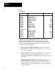
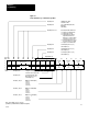
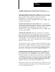
Table 3.C
Loop
Block W
ords
Word
Title Abbreviation
Standard Features
W18(W38)
W19 (W39)
W20 (W40)
W21 (W41)
W22 (W42)
W23 (W43)
W24 (W44)
W25 (W45)
W26 (W46)
W27 (W47)
W28 (W48)
W29 (W49)
Loop Control W
ord A
Loop Control W
ord B
Input Filter Time Constant
Maximum Negative Error
Maximum Positive Error
Dead Band
Integral Gain
Derivative Gain
Integral T
erm Limit
Derivative T
erm Limit
Minimum Output Limit
Maximum Output Limit
T
A
EMN
EMP
DB
K
I
K
D
V
I
MAX
V
D
MAX
VMIN
VMAX
Expanded Features
W30 (W50)
W31 (W51)
W32 (W52)
W33 (W53)
W34 (W54)
W35 (W55)
W36 (W56)
Expanded Control W
ord
Minimum Scaling V
alue
Maximum Scaling V
alue
Feedforward Of
fset
Feedforward Gain
Lead T
ime Constant
Lag T
ime Constant
SMIN
SMAX
FFO
K
F
TB
TC
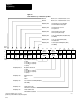
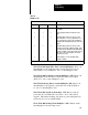
W18 (W38) Loop Control Word A. This word together with loop
control word B, W19 (W39), and loop expanded control word, W30
(W50), select the configuration for the loop. Bits 17 through 00 of loop
control word A are defined below and summarized in Figure 3.6 for loop
1 word W18 and loop 2 word W38.
W18 (W38) B17, B16 Block Identifiers. These two bits identify
this block as the loop block. B17 = 0 and B16 = 1 for loop 1. (For
loop 2, B17 = 1, B16 = 0.)
W18 (W38) B15 Source of Process Variable. Reset to 0 selects the
analog input as the process variable input for the loop. Set to 1
selects the value SET PV in word W09 (W16) as the process variable
for the loop.
W18 (W38) B14 Square Root of Process Variable. Reset to 0
inhibits the square root function. Set to 1 enables the normalized
square root of the process variable, (square root of PV x (square root
of 4095). Square root allows the linearization of differential pressure
type flow transducers.