
Instruction Manual

Aseembly and Installation
Chapter 2
229
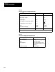
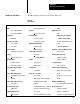
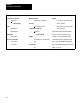
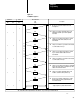
The PID module specifications are listed in Table 2.G.
Table 2.G
Specifications
Process
V
ariable Inputs
Digital Resolution Maximum Current
Number 12binary
, 1 part in 4095
250mA
process variable input 1
Accuracy
Maximum Power
process variable input 2
+
0.1% of range at 25
0
C3VA
Configuration
Input Impedance
Digital Inputs (from manual
Differential
250 ohms (current)
manual control station)
Range (userselectable)
4.7 megohms (voltage)
T
wo independent inputs for moni
+4 to +20mA
Maximum Allowable Input
toring
+1 to +5V dc
+
30mA (current)
Power Requirements
Digital Resolution
25V rms (voltage) Backplane or External (Digital Circuits)
12bit binary
, 1 part in 4095
T
emperature Coefficient
1.2A at +5V dc
Accuracy +
50 ppm/
0
C
External (Analog Circuits)
+
0.1% of range at 25
0
C
Analog Outputs 100mA A
T +15V dc
Input Impedance
Number
100mA at 15V dc
250 ohms (current) analog output 1
Loop Update T
ime
10 megohms (voltage)
analog output 2 100msec, typical
Common Mode Rejection Ratio
Configuration
Ambient T
emperature Ratings
70dB DC
Single ended
Operation 0
0
C to 60
0
C (32
0
F to
Common Mode V
oltage Range
Range (userselectable)
140
0
F
+
200V with respect to module +4 to +20mA
Storage 40
0
C to 85
0
C (40
0
F to
common
(With output common internally
185
0
F)
Common Mode Input Resistance referenced to power supply Relative Humidity Rating
2.5 megohms
common
5% to 95% (without condensation)
Input Frequency Respnse
the output will drive up to a 500 ohm
Electrical Isolation
3dB at 1kHz
load over the full current range.
[1]
1500V rms (transient
Maximum Allowable Input
+1 to +5V dc
(Isolation is achieved by
+
30mA (current)
(500 ohms minimum load resistance
optoelectronic coupling between I/O
Module Specifications