
Instruction Manual

Aseembly and Installation
Chapter 2
227
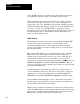
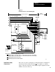
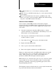
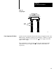
Figure 2.11
Keying
Diagram
2
4
6
8
10
12
14
16
18
20
22
24
26
28
30
32
34
36
2
4
6
8
10
12
14
16
18
20
22
24
26
28
30
32
34
36
Left
Connector
Right
Connector
Keying
Bands
11106
Upper Backplane Connectors
0PID Module 1
Single Module Group
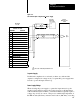
Isolation must be maintained between the analog and digital circuits of the
PID module to minimize electrical noise interference. Therefore, separate
power supplies must be used for the analog +
15V dc supply and for the
digital +5V dc supply.
The requirements for the customer +
15V dc power supply and for the
optional +5V dc power supply are listed in Table 2.E and Table 2.F,
respectively.
Power Supply Specifications