
Instruction Manual

Assembly and Installation
Chapter 2
226
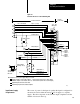
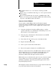
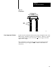
Plastic keying bands shipped with the I/O chassis should be used. The
position of the keying bands on the upper backplane connector must
correspond to the mating slots on the module connector.
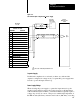
Refer to Figure 2.11. Using needle-nose pliers, place the keying bands on
the backplane connector between these numbers:
Slot 0 (left)
8 and 10
18 and 20
slot 1 (right)
2 and 4
28 and 30
The position of the keying bands can be changed if subsequent system
design requires the module to be moved to a different location.