
Instruction Manual

Aseembly and Installation
Chapter 2
219
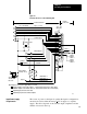
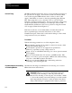
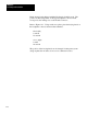
Figure 2.9
Internal
Connections to the Field Wiring Arm
Input 1 (+ Lead)
Input 2 (+ Lead)
Tieback Input 1
Tieback Input 2
250
250
E11 E12
Analog Output 1
Module Common
Analog Output 2
+15V DC
15V DC Common
-15V DC
+
-
Standard
Compliance
E22 E21
Manual Mode 1
Manual Mode 2
Manual Request
Contact Output
(normally closed)
30V peak
1/4 AMP Max.
Max. 3VA
Station 2
Station 1
Manual
Request
Station 1
Manual
Request
Station 2
Additional
Standard compliance selects module common as 15V DC Common (500 max for current outputs.)
Additional compliance selects module common as -15V DC Common (1250 max for current outputs.)
Programming plugs inserted for current mode.
Programming pl ugs inserted for standard compliance.
+
-
NOTE: Optional +5V DC power supply wiring is not shown.
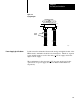
1771 - WF
Wiring Arm
1771 - PID Module
External
Connections
Internal Connections
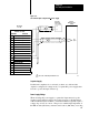
11105
2
1
2
3
1
3
1
2
3
4
5
6
7
8
9
10
11
12
13
14
15
16
17
18
Ω
Ω
Ω
Ω
OptoIso
The source of power for the input loop when the input is configured for
current mode can be either the analog +
15V dc supply or a separate
supply. The choice depends on the selected output compliance and the
number of devices in the loop.
Input Power Supply
Requirements