
Instruction Manual

Application Example 2, Periodic Block
Transfer
Appendix C
C37
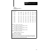
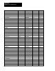
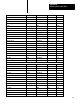
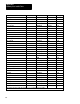
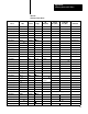
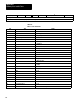
Table C.D
PLC3
File Storage Addresses
(shown in hex)
Start = WB000:0000
W
ord number
01234567
00000 0001 E180 0000 0001 0012 0000 3303 0050
00008 0000 0000 0000 0026 0000 0000 0000 0000
000116 0000 0000 4000 0000 0000 0000 4095 0000
00024 0000 0000 0000 0000 0000 4095 0000 0000
00032 0000 0000 0000 0000 0000 0000 8000 0000
00040 0000 0000 0000 0000 0000 0000 0000 0000
00048 0000 0000 0000 0000 0000 0000 0000 0000
00056 0000 0000 0000 0001 0000 0450 2203 1101
00064 1100 1100 0000 0000 0000 0000 0000 0000
00072 0000 0000 0000 0000 0000 0000 0000 0000
Dynamic Block binary file 0, words 1 thru 17
start location: 00000000 00000001 in binary
, 0001 in hex
Loop 1 Block binary file 0, words 18 thru 36
start location: 00000000 00010010 in binary
, 0012 in hex
Loop 2 Block binary file 0, words 38 thru 56
start location: 00000000 001001
10 in binary
, 0026 in hex
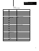
Status Block binary file 0, word 57 thru 74
Input Buf
fer binary file 2, words 0 thru 20
Block T
ransfer Control File Binary file 3
Module Location: rack 2, module group 1
NOTE: Block transfer control file must be the same for the read and write block transfer instructions.
Binary file 0 word 0 is used to store the dynamic block start address (rung l3 in the continuous block
transfer program, rung 23 in the periodic block transfer program).