
Instruction Manual

Application Example 2, Periodic Block
Transfer
Appendix C
C22
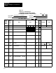
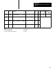
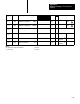
Figure C.5
Worksheet
2 for Loop 1 Block
AllenBradley Programmable Controller
1771PD Module W
orksheet 2
Loop 1 Block
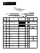
Project Name:
Page of
Designer: Data Table Size:
Processor:
DATA TABLE WORD USAGE From to
23
Example Program PLC-2/30
540
300 322
Data
Table
Word
Address
Module
Word
#
Name Value Range
BCD
or
BIN
Multiplier Sign
1
17 14
13 10 07 04 03 00
300
W18 Loop
1 Control W
ord A
01 0
0 0 0 1 1 0 0 0 0 0 0 0 0
FFFF
4300
2
301
W19
Loop 1 Control Word B
0
1 1 0 0 0 0 0 0 0 0 0 0 0 0 0
FFFF
6000
2
302
W20
Input Filter T
ime Constant 1
TA1
0|1|9|
0
99.99
x10
W19 B12
x1
3
303
W21
Maximum Negative Error 1
EMN1
4|0|9|
5
4095
304
W22
Maximum Positive Error 1
EMP1
4|0|9|
5
4095
305
W23
Dead Band 1
DB1
0|0|1|
5
4095
306
W24
Integral Gain 1
K
I
1
0|6|0|
0
9.999
W19 B03,02
x1
4
307
W25
Derivative Gain 1
K
D
1
0|0|0|
0
99.99
W19 B01,00
4
310
W26
Integral T
erm Limit 1
V
I
MAX1
4|0|0|
0
9999
311
W27
Derivative T
erm Limit 1
V
D
MAX1
4|0|9|
5
9999
312
W28
Minimum Output Limit 1
VMIN1
0|0|0|
0
4095