
Instruction Manual

Application Example 2, Periodic Block
Transfer
Appendix C
C20
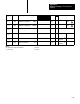
Figure C.4
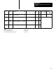
Worksheet
1 for Dynamic Block
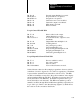
Project Name:
Page of
Designer: Data Table Size:
Processor:
DATA TABLE WORD USAGE From to
Example Program PLC-2/30
540
257 277
13
AllenBradley Programmable Controller
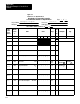
1771PD Module W
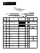
orksheet 1 Dynamic Block
Data
Table
Word
Address
Module
Word
#
Name Value Range
BCD
or
BIN
Multiplier Sign
3
17 14
13 10 07 04 03 00
257
W01 Master
Control W
ord
1 1 0 1 0 0 0 0 0 0 0 0 0 0 0 0
FFFF
D000
4
260
W02
Control W
ord F000
261
W03
Dynamic Block Start Address
0|2|5|
7
FFFF
262
W04
Loop 1 Block Start Address
0|3|0|
0
FFFF
263
W05
Set Analog Output 1
SET OUT1
2|0|4|
8
4095
1
264
W06
Set Point 1
SP1
3|0|7|
2
4095/
9999
2
x10
W19B06
x1
W19 B07
5
+
265
W07
Proportional Gain 1
K
P
1
4|5|5|
0
99.99
W19 B05.04
x1
6
266
W08
Bias 1
BIAS1
0|0|9|
6
9999
267
W09
Set Process V
ariable 1
SET PV1
0|0|0|
0
4095
1
270
W10
Set Feedforward Input 1
SET FFI1
0|0|0|
0
4095
1
271
W11
Loop 2 Block Start Address
0|3|2|
4
FFFF
272
W12
Set Analog Output 2
SET OUT2
1|0|2|
4
4095
1