
Instruction Manual

Application Example 2, Periodic Block
Transfer
Appendix C
C19
Bit 10 = 0 Integral output limiting is not used.
Bits 07,06 = 1 Proportional error is squared.
Bits 05,04 = 0 Integral error is squared.
Bit 03 = 0 Derivative error is not modified.
Bit 02 = 0 Derivative output is not limited.
Bit 01 = 0 PID output is not held.
Bit 00 = 0 Bias is not held.
Loop 2 Control Word B W39
Bit 17 = 0 Bias is added to the output.
Bit 16 - 0 Output limiting is not used.
Bits 15,14,13=1 If a soft fault occurs, output 2 is set to
maximum.
Bit 12 = 0 Digital filter time multiplier is x1.
Bit 11,10=0 Lead/lag time x1.
Bit 7 = 0 Set point sign is positive.
Bit 06 = 0 Setpoint multiplier is x1.
Bits 05 = 1,04=0 Proportional gain multiplier is x10
Bits 03,02=0 Integral gain multiplier is x1.
Bits 01,00=0 Derivative gain multiplier is x1.
Loop 2 Expanded Control Word W50
Bit 17 = 1 Process variable is scaled.
Bit 16 = 1 Set point is scaled.
Bit 15 = 1 Error is scaled.
Bits 14 thru 00=0 None of these features are used.
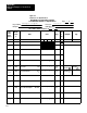
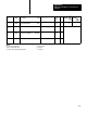
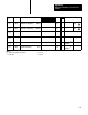
Selected feature values for this example program have been recorded in
worksheets 1,2 and 3. (figures C.4, C.5 and C.6, respectively.) Worksheet
1 represents the dynamic block (data table words 257-277
8). The PID
module word numbers correspond to the position numbers on the display
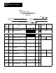
and are numbered W01 through W17. Worksheet 2 represents the loop 1
block (data table words 300-322
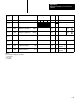
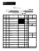
8). Worksheet 3 represents the loop 2
block (data table words 324-346
8). The PID word numbers (position
numbers) are W18 through W36 and W38 through W56, respectively for
loop 1 and loop 2. Refer to the data table map (figure C.3) which shows
the locations of the consecutive data blocks.