
Instruction Manual

Application Example 2, Periodic Block
Transfer
Appendix C
C18
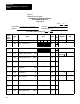
Bit 11 = 1 Dead band is set to 15 in word W23.
Bit 10 = 1 Integral output is limited to 4000 in
wordW26.
Bits 07,06 = 0 Proportional error is not modified.
Bits 05, 04 = 0 Integral error is not modified.
Bit 03 = 0 Derivative error is not modified.
Bit 02 = 0 Derivative output is not limited.
Bit 01 = 0 PID output is not held.
Bit 00 = 0 Bias is not held.
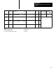
Loop 1 Control Word B W 19
Bit 17 = 0 Bias is added to the output.
Bit 16 = 1 Output is limited to 4050 in word W28 for
loop 1.
Bit 15 = 1 Soft fault response is to continue PID
control.
Bit 14 = 0 Soft fault response is to continue PID
control.
Bit 13 = 0 Soft fault response is to continue PID
control.
Bit 12 - 0 Digital filter time x1.
Bits 11,10 = 0 Lead/lag time multiplier is x1.
Bit 07 = 0 Set point sign is positive.
Bits 05,04 = 0 K
P
multiplier is x1.
Bits 03,02 = 0 K
I
multiplier is x1.
Bits 01,00 = 0 K
D
multiplier is x1.
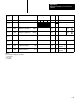
Loop 1 Expanded Control Word W30
Bit 17 = 1 Process variable is scaled.
Bit 16 = 1 Set point is scaled.
Bit 15 = 1 Error is scaled.
Bits 14 thru 00=0 None of these features are used.
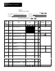
Loop 2 Control Word A W38
Bit 17 = 1 Block identifier must be 1.
Bit 16 - 0 Block identifier must be 0.
Bit 15 = 0 Source of the process variable input is the
analog input.
Bit 14 = 1 Square root modifies the analog input.
Bit 13 = 0 Error is positive (SP-PV).
Bit 12 = 0 Error limiting is not used.
Bit 11 = 1 Dead band is set to 20 in word W43.