
Instruction Manual
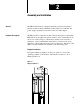

Assembly and Installation
Chapter 2
26
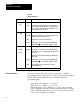
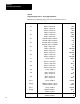
Table 2.D
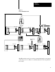
Programming Plug Positions: Analog (righthand) Board
Mark the programming plug position for each function below.
Location Function Position
E1 Output
2, current mode
Output 2, voltage mode
LEFT
RIGHT
E2
Output 2, current mode
Output 2, voltage mode
LEFT
RIGHT
E3
Output 1, current mode
Output 1, voltage mode
LEFT
RIGHT
E4
Hard fault* output 2, minimum
Hard fault* output 2, maximum
IN
OUT
E5
Hard fault* output 1, to minimum
Hard fault* output 1, to maximum
IN
OUT
E6
Output 1, voltage mode
Output 1, current mode
TOP
BOTTOM
E7
Output 2, voltage mode
Output 2, current mode
TOP
BOTTOM
E8
Output 1, voltage mode
Output 2, current mode
TOP
BOTTOM
E9
Factory configured
RIGHT
E11 T
ieback 1, current mode
T
ieback 1, voltage mode
IN
OUT 1
E12 T
ieback 2, current mode
T
ieback 2, voltage mode
IN
OUT 1
E13
Factory configured
LEFT
E14
Input 2, current mode
Input 2, voltage mode
IN
OUT 1
E15
Input 1, current mode
Input 1, voltage mode
IN
OUT 1
E16,17
Factory configured
BOTH IN
E18
[2]
Additional compliance (15V dc)
Standard compliance (OV dc)
LEFT
RIGHT
E19, 20 Factory configured
BOTH IN
E21
[2]
Additional compliance
Standard compliance
OUT 1
IN
E22[ 2 ]
Additional compliance
Standard compliance
OUT [1]
IN