
Instruction Manual
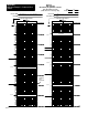
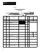
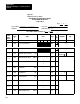
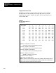

Application Example 1, Continuous Block
Transfer
Appendix B
B17
272
W12
Set Analog Output 2
SET OUT2
0|0|0|
0
4095
1
273
W13 Set
Point 2
SP2
0|0|0|
0
4095/
9999
2 x10
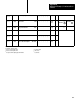
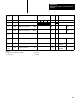
W39
B06
x1
W39 B07
5
+
274
W14
Proportional Gain 2
K
P
2
0|0|0|
0
99.99
W39 B05, 04
x1
6
275
W15
Bias 2
BIAS2
0|0|0|
0
9999
276
W16
Set Process V
ariable 2
SET PV2
0|0|0|
0
4095
1
277
W17
Set Feedforward Input 2
SET FFI2
0|0|0|
0
4095
1
NOTES:
For
the BCD or Binary column:
1
denotes selection by W 01 B12
4
record Hex value
2
denotes selection by W 01 B1
1
5
circle choice
3
also represents the displayed position number
6
record value