
Instruction Manual
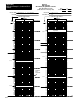
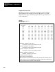

Application Example 1, Continuous Block
Transfer
Appendix B
B14
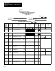
Bit 10 is controlled in rung 19
Bit 07 = 0 Loop time is reported in the status monitor
byte.
Bit 06 Load bit is controlled by user program.
Bit 05, 04 Verify bits must be 0.
Bit 03 = 0 Enter bit is controlled by user program.
Bit 02 = 0 Set output bit is not used.
Bit 01 = 0 Analog output is set to programmed value if
loss of PV input occurs. Bit 01 is controlled
in rung 17.
Bit 00 = 0 Manual request bit is not used.
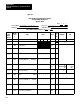
Loop 1 Control Word A W18
Bit 17 = 0 Block identifier must be 0.
Bit 16 = 1 Block identifier must be 1.
Bit 15 = 0 The source of the process variable input is
the analog input.
Bit 14 = 0 Square root is not used.
Bit 13 = 0 Error is positive (SP-PV).
Bit 12 = 0 Error limiting is not used.
Bit 11 = 1 Dead band is set to 15 in word W23.
Bit 10 = 1 Integral output is limited to 4000 in word
W26.
Bits 07,06 = 0 Proportional error is not modified.
Bits 05,04 = 0 Integral error is not modified.
Bit 03 = 0 Derivative error is not modified.
Bit 02 = 0 Derivative output is not limited.
Bit 01 = 0 PID output is not held.
Bit 00 = 0 Bias is not held.
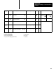
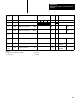
Loop 1 Control Word B W19
Bit 17 - 0 Bias is added to the output.
Bit 16 = 1 Output is limited to 4050 in word W29.
Bit 15 = 1 Soft fault response is to continue PID
control.
Bit 14 = 0 Soft fault response is to continue PID
control.
Bit 13 = 0 Soft fault response is to continue PID
control
Bit 12 = 0 Digital filter time is multiplied x1.
Bit 11 = 0 Lead time constant TB is multiplied x1
Bit 10 = 0 Lag time constant TC is multiplied x1