
Instruction Manual
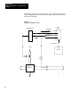
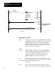

Application Example 1, Continuous Block
Transfer
Appendix B
B11
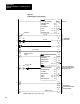
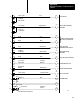
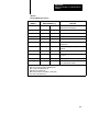
Table B.B
Functional
Bit/Word Descriptions
PROGRAM
ADDRESS
MODULE ADDRESS [1]
FUNCTION
257/01 W01 B01
When set, allows a programmed value to be
downloaded to analog output 1.
275/03 W01 B03
Enter bit
257/06 W01 B06
Load bit
350/12 W58 B12
Ready bit
353/04 W61 B04
Powerup bit
353/05 W61 B05
Set when manual control station is in the
manual mode.
353/07 W61 B07
Set when analog input 1 has gone below
minimum.
353/12 W61 B12
Load/enter complete bit
263
8
W05
Analog output 1 download from the PC
processor.
264
8
W06
Loop 1 setpoint
351
8
W59
Contains data table location of the next data
block required by the module.
[1]
W01 master control word (dynamic block)
W05 word for set analog output 1 (dynamic block)
W06 set point word (dynamic block)
W58 alarm word (status block)
W59 word for next block start address (status block)
W61 status word (status block)