
Instruction Manual
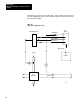
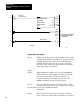

Application Example 1, Continuous Block
Transfer
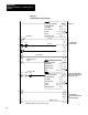
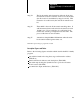
Appendix B
B10
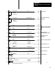
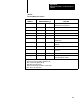
Table B.A
Data
Table Information
W
ord Address
Number
of W
ords
Input Buf
fer Location
words 233
8
256
8
Dynamic Block Location
words 257
8
277
8
Loop 1 Block Location
words 300
8
322
8
Loop 2 Block Location
words 324
8
346
8
(available for other storage)
Status Block Location
words 347
8
370
8
Timers/Counters
043
8
, 044
8
, 143
8
, 144
8
Block T
ransfer Instructions
030
8
, 031
8
, 130
8
, 131
8
FileT
oFile Move Instructions
040
8
, 041
8
, 140
8
, 141
8
Storage W
ords
032
8
, 033
8
, 037
8
, 050
8
Total
Pushbutton/Selector Switches
PB 1
1
1/00, PB 1
1
1/01, SS 1
11/06
Output Indicators
012/00, 012/01, 012/02, 01203, 012/04
Storage Bits
050/00, 050/01
Module Location
rack 1, module group 3: 113 input image table, 013
output image table
PC Processor T
ype
PLC2/30
Ladder Diagram Program Length
73 words
20
17
19
18
4
4
4
4
90