
Instruction Manual
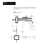
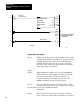

Application Example 1, Continuous Block
Transfer
Appendix B
B5
350
13
L
257
06
PUT
131
257
G
Storage Word
050
00
Power-up Bit
Load
Load/Enter
One-Shot Bit
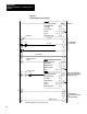
SETS LOAD BIT
350
13
012
03
Power-up Bit Output Indicator
MODULE NOT INITIALIZED
INDICATOR
353
04
Power-Up
Complete BIt
350
12
U
257
06
Ready Load
350
12
L
257
03
Ready
Enter
350
12
U
050
00
Ready One-Shot Bit
READY BIT RESETS LOAD
BIT AND SETS ENTER BIT
READY BIT RESET
LOAD/ENTER ONE-SHOT BIT
353
12
012
01
Load/Enter
Complete Bit
Output Indicator
350
12
U
257
03
Ready Enter
353
07
257
01
Loss of PV #1 Set Analog
Indicating Bit Output Bit
353
05
012
04
Manual Mode
Indicator Output Indicator
111
06
257
10
Selector Switch
Soft Fault Reset Bit
111
01
PUT
264
000
110
024
Thumbweels
W06
G
351
257
Word
59
Power-Up Bit
350
13
G
037
257
PUT
131
257
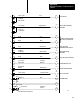
Write Block
Transfer
Dynamic Block Start Address
LOAD/ENTER FAILED
INDICATOR
READY BIT RESETS ENTER BIT
SET ANALOG OUTPUT #1
MANUAL MODE INDICATOR
SOFT FAULT RESET
SETPOINT ENTRY
10*
11
12*
13*
14*
15
16*
17
18
19
20
21*
22*
11148