
Instruction Manual

Chapter 5
58
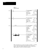
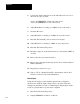
Control bits can be set by loading hex values into control words. Hex
values which must be set as part of the calibration procedures are listed in
Table 5.B and described in a. through d. as follows:
a. Calibration bit B13 in word W01 must be set at module power
up to place the PID module in calibration mode. Load C800
hex into word W01.
b. The input to be calibrated in sections titled Voltage Reference
and Current Inputs through section titled Output Amplifier,
Voltage Adjustments is selected by loading the corresponding
hex value into word W02.
c. The full-scale SET OUT value of OFFF hex must be loaded into
word W05 for loop 1 (1 word W12 for loop 2) for calibration
procedures in sections titled Current Inputs and Tieback Current
Inputs.
d. The set output bit B01 for loop 1 (B02 for loop 2) must be set in
word W01 to download the SET OUT value of OFFF hex to the
PID module in calibration procedures in sections titled Current
Inputs and Tieback Current Inputs.
Table 5.B
Calibration
V
alues
Description
Procedure Word
Hex V
alue
Calibration bit
Power up
W01 C800
Input select
analog input 1
tieback input 1
analog input 2
tieback input 2
5.4.2
and
5.4.5
thru
5.4.7
W02
W02
W02
W02
AB ISA
0000 0001
4000 4001
8000 8001
C000 C001
SET OUT value
loop 1
loop 2
5.4.5
and
5.4.6
W05
W12
OFFF
OFFF
Set Output bit
loop 1
loop2
5.4.5
and
5.4.6
W01
W01
C802
C804