
Instruction Manual

Chapter 5
53
Installation
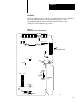
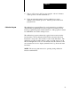
Before installing the analog circuit board in the I/O chassis for calibration,
record the initial positions of the programming plugs on . The
programming plugs should be returned to these positions at the
completion of the calibration procedure.
Figure 5.2
Calibration
Locations (Analog Board)
R
3
R
4
R
5
R
6
R
7
R
8
R
9
R
10
R
11
R
12
R
16
R
17
R
18
R
19
TP1
TP3
TP2
V
I
VI
VI
VI
E3
E6
E7
E8
E5
IN
or
OUT
V
I
V
I
E2
E1
E4
IN
or
OUT
E10
E13
E16 E17
E19 E20
E21
IN
or
OUT
E22
E23
E24
Backplane
External
IN
or
OUT
E11 E12
IN
or
OUT
E15
E14
TP4
E9
R58
R59
R60
R61
R62
R63
R64
R65
R66
R67
R68
TP5
E18
Additional
(-15V DC)
Standard
(0V DC)
Compliance
Field Wiring
Arm
Stake
Pins
11139
*
*
*
*
*
*
*
*
Plug
Pin
Factory Configured Plug