
Instruction Manual

Chapter
5
51
Calibration
The PID module is calibrated before it leaves the factory. The calibration
of the module should be checked yearly. It can be returned to
Allen-Bradley Systems Division for factory calibration. Revision B and
later models can be calibrated using the procedures described in this
chapter.
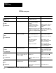
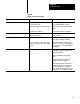
The following test equipment and parts should be available. Some of this
equipment can be borrowed from the system installation or an
independent test station can be used.
DC
V
oltage Standard
+10V
, 0.1mV resolution Fluke 342A, or equivalent
Digital V
oltmeter
5 1/2 digit, 0.01% accuracy
Keithly 191, Fluke 8300A, or
equivalent
Precision Resistor AllenBradley Systems Division
250 ohms
+
0.02% 1/4 watt
PN 61099601
Resistor
1000 ohms
+
l% watt
numerous sources
Industrial T
erminal
AllenBradley system terminal or
spare, compatible with test PC.
Programmable Controller
System PC or space
Analog Power Supply
AllenBradley Power Supply (cat.
no. 1770P1) +15V dc, 15V dc,
system supply or spare
Chassis Power Supply
AllenBradley (cat. no. 1771P2)
system supply or spare
I/O Chassis
AllenBradley (cat. no. 1771A1,A2
or A4) system chassis or system
spare
Extender Board AllenBradley (cat. no. 1771EX)
Field Wiring Arm AllenBradley (cat. no. 1771WF)
system spare
Alignment T
ool
pottweeker"
Newark Electronic PN 35F616 or TV
duplex Aligner with plastic shaft, or
equivalent
General
Test Equipment